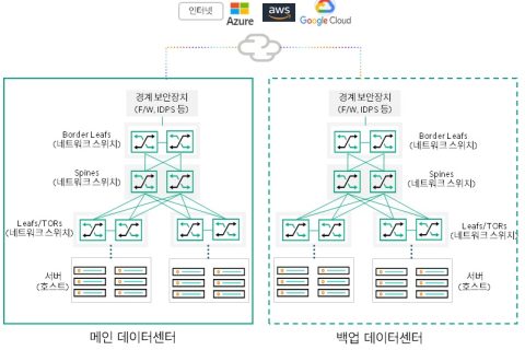
Data center design is multi-layered, starting from the NIC cards of the servers to the uplinks and switches. RedundancyIncludes:.
This redundancy is essential, but at the same time Network loops, broadcast storms, and network outagesIncreases the risk of.
Today, we'll learn key technologies to mitigate these risks and build high-performance, redundant L2 data centers.
1. Structure of a Collapsed Core L2 Data Center
Data centers require redundancy of switches and links for high availability, which complicates the physical connectivity structure.
In the unified core L2 topology Virtual Switching eXtension (VSX) and Link Aggregation Group (LAG) Technology plays a key role in simplifying this complexity.
Simplification through VSX and LAG
- VSX: A pair of switches Single switch at Layer 2It works like this, integrating devices into a single logical entity.
- LAG (Link Aggregation Group): Multiple physical links one logical linkTie it together.
The benefits of this combination of technologies include:.
- Ensure high availability: Even if a switch or cable fails, the network can still be accessed. Active pathMaintain.
- Performance improvements: Improves network performance by allowing load balancing across multiple links and devices simultaneously.
- Simplify logical topology: Easier to manage and less prone to errors.
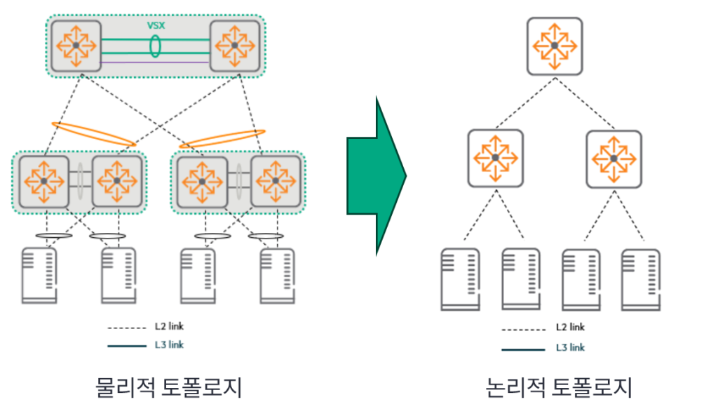
Why Loop Prevention Technology Is Still Needed
Although VSX and LAG simplify the network, Spanning Tree Protocol (STP) and loop-protection technologies are still required.
Loop prevention techniques are still needed due to incorrect cable connections, configuration errors, or external device issues.
2. Redundant server connection options
When connecting servers to a network, you need to consider link redundancy and performance.
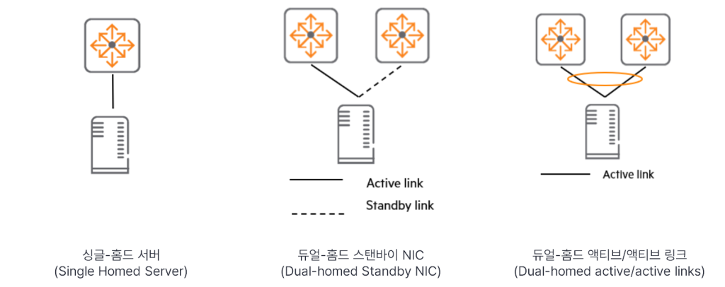
| Connection Options | explanation | Redundancy | Recommendations |
| single-homed server | Single connection to access switch | doesn't exist | Not recommended |
| Dual-homed standby NIC | NIC Teaming: Only one active, the rest are on standby. | When a link fails, the standby link is activated. | |
| Dual-homed active/active link | NIC Teaming: Use two or more connections simultaneously (load balancing). | Provides redundancy and better performance. | Most recommended method (Connect servers to different switches to protect against switch failure) |
blade server
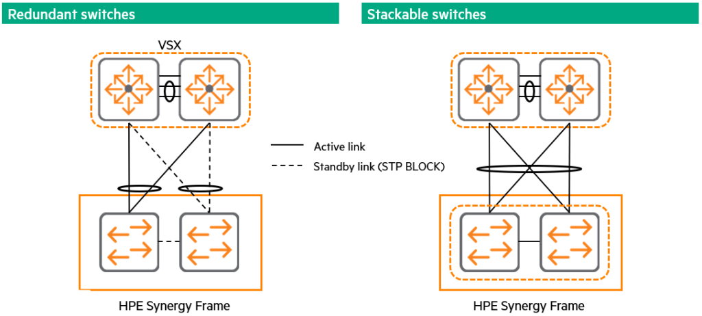
blade serverrefers to systems that use built-in switches instead of standard NICs, such as HPE Synergy.
These switches can act as a single bypass or provide advanced configurations and features.
For redundancy, we recommend configuring a LAG by stacking internal switches.
3. Link Aggregation Group (LAG) Details
LAG is a way to group multiple ports into one virtual link to increase bandwidth.
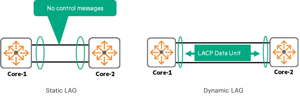
| LAG type | How it works | Features and Recommendations |
| Static LAG | Without exchange of control information between devices Configure independently. | Not recommended. Failed to detect incorrect configuration of peer Temporary loopIt may cause unexpected behavior. |
| Dynamic LAG (LACP) | 802.3ad standard. LACP Data UnitsSet/maintain LAG by exchanging . | Recommended method. Detects link failures and ensures that port members are connected to the same device to prevent network problems. |
LACP Data Unit The message contains:.
- System ID: Unique ID for switch identification
- Operational Key: Unique values for identifying LAG
LAG Interface Requirements
Interfaces that are mapped to the same LAG have the following: agreementMust do.
- Duplex mode
- Link speed
- Media
If you try to map a mismatched interface to a LAG, AOS-CX displays a warning.
For example, interface 5, which has a speed of 10 Gb/s, cannot be added to LAG10, which has a base speed of 1 Gb/s.In AOS-CX, each link aggregation group is Up to 8 individual portscan have.
show capacitiesCheck the switch capacity using the command.
Load Balancing Algorithm
The switch is Hash algorithmUse to distribute traffic load across multiple physical interfaces.
Hash algorithm: It is a one-way function that gives an output (y) when you input (x), but you cannot infer the input by looking at the output.
The same input always produces the same result.
Input value: The switch is Packet header informationis used as input to the hash function.
- Layer 4 TCP/UDP ports
- Layer 3 Source and destination IP addresses
- Layer 2 Source and destination MAC addresses
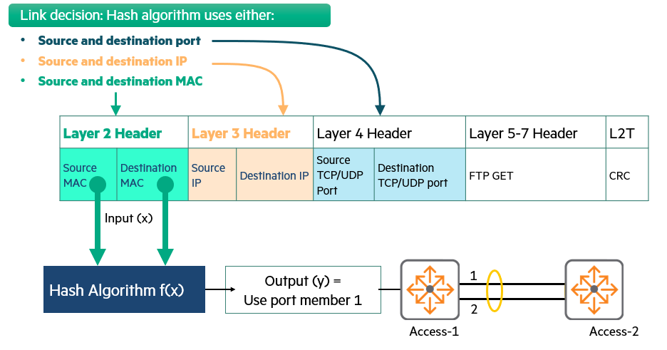
functioning: The switch determines which member port the packet will use based on the result obtained through the hash algorithm.
specific Origin-destination combinationAll packets with are always Same physical portYou will use .
4. Loop prevention and STP optimization
Even though VSX and LAG simplify the logical topology, the network is still Cabling error나 misconstructionmust be protected from.
Spanning Tree Protocol (STP) Operation Overview
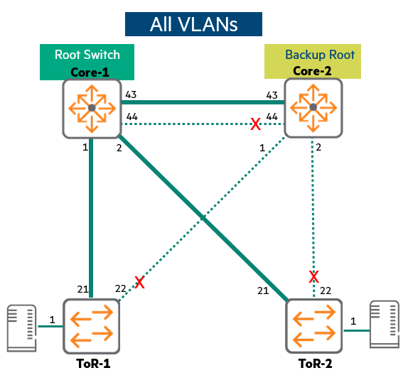
STP maintains redundancy Loop-free networkwas developed to build and maintain.
- How it works: STP automatically disables redundant links to create a loop-free topology and prevent MAC table instability.
- Convergence: STP will move towards a new active link topology when a failure occurs. ConvergenceConvergence means that all network devices agree on a new network path.
- root bridge: In an STP domain, one switch is elected as the Root Bridge, and all paths grow from this Root Bridge.
Evolution of STP
| STP version | characteristic | Key Drawbacks and Developments |
| 802.1d (original STP) | Timer-based. Only the root switch generates a “hello” packet every 2 seconds. | Slow. Convergence takes a long time with the default Max Age timer (20 seconds) and Forward Delay timer (15 seconds). It is now outdated and not recommended for use. |
| RSTP (Rapid STP) | Developed in 1998. All switches generate hello packetsProvides a true keep-alive mechanism. | speed. Response in seconds. No need for slow timers (Max Age, Forward Delay). |
| MSTP (Multiple STP, 802.1s) | Improve RSTP Multiple loop-free topology instancesBuild. | Optimal path and load balancingto enable. |
💡 AOS-CX switchMSTP runs by default and behaves like RSTP if no special configuration is made.
MSTP Details: Common vs. Multi-Instance
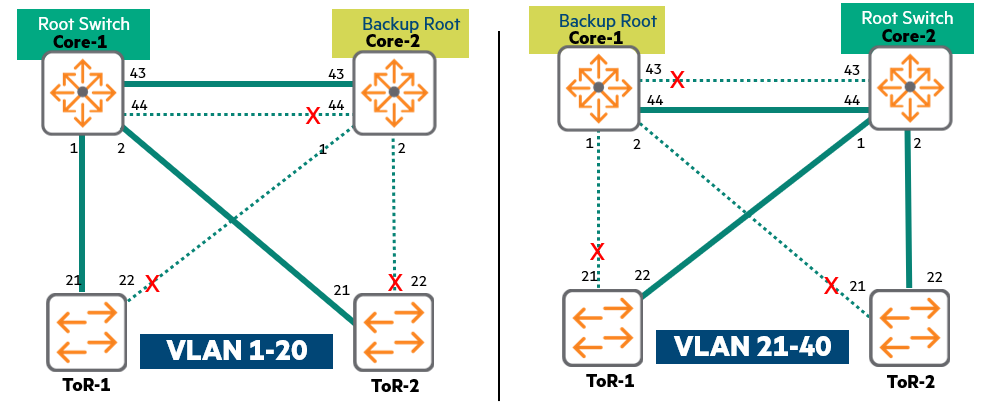
Common Spanning Tree (CST): throughout the network One STP instanceOnly defines (VLANs are not considered).
- disadvantage: Load balancing not working, sub-optimal pathing, low link utilization.
Multiple Spanning Tree (MSTP): To distribute VLAN traffic Multiple instances. Different VLANs are configured to have different root bridges, allowing them to alternate between active and standby links to better utilize resources.
Single-Instance MSTP in VSX/LAG Environments
With VSX and LAG, you can connect to any switch Already active It's a state.
- Multiple instancesThe complex setup that creates There is no benefit.
- Because all traffic will use the same link and converge to the same root bridge, single instanceIt is most efficient to just prevent loops.
5. STP Protection: Ensuring Network Security and Stability
A security mechanism to protect STP configuration from interference or faulty devices.
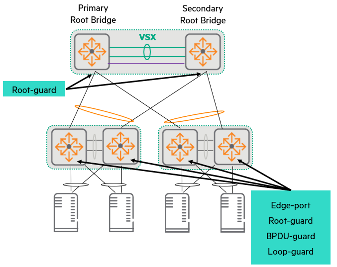
Root-guard (root guard)
- purpose: today Active topologyProtects.
- functioning: Prevents another switch from replacing the root bridge election by broadcasting better information (superior BPDUs) than the current root bridge.
- Applicable location: Since the core switch is expected to act as a root, Access switch or server portIt should be configured on ports where root election is not expected, such as:.
BPDU-Guard
- purpose: Protects the active topology by preventing spoofed BPDU packets from entering the network.
- Applicable location: Not running STP Edge Port (applies to the port connected to the end-user device).
- functioning: When an STP BPDU packet is received on a protected port, BPDU guard disables the portand send a warning.
This protects your network from accidentally connected switches or malicious attacks.
⚠️ caution: like HPE Synergy blade serverIt has a built-in switch that can generate BPDUs.
Loop guard Be aware that enabling (loop guard) on these ports may disable the switch port, making the server inaccessible.Although Loop-guard is mentioned in the BPDU-guard description section now, BPDU-guard is generally applicable.
However, you must be aware of the special nature of blade servers.
Edge-port (management edge port)
- purpose: Addresses client onboarding issues by preventing network edge ports from fully participating in STP.
- Problem: When a port participates in the entire STP process DHCP allocation timeoutIna IP address allocation delay, Client authentication issuemay occur.
- solve:
spanning-tree port-type admin-edgeUse the command to open the port STP managed edge portsSet to .
This command removes the port's participation in STP interaction when onboarding the device. Faster onboardingIt enables.
This time, we are securing high availability of the data center. stabilityWe covered how to maintain it.
VSX와 LAG The technology provides switch and link redundancy while solving complex physical topologies. Simple and efficient logical structureIt plays a key role in converting to . We also looked at how to connect servers and how to prevent network loops.
The combination of these technologies creates a redundant environment designed to increase data center availability. High-performance and non-stop operating environmentwill be optimized.