Because a switch is a Layer 2 device, its ports can only perform Layer 2 functions and protocols, such as becoming members (member ports) of each VLAN or forwarding frames.
When an endpoint terminal is connected to a port used as a Layer 2 interface, L2 frames are forwarded based on the destination Layer 2 MAC address.
※ Since the AOS-CX switch port is basically a Layer 3 interface, you must use the “no routing” command.
But how do we route between VLANs? AOS-CX switches are multilayer switches. Therefore, they have both Layer 2 internal switching and Layer 3 internal routing capabilities. We need a way to connect each Layer 2 VLAN through internal routing.
Inter-VLAN Routing
Types of multi-layer interfaces
To route between VLANs, you must create a Switch Virtual Interface (SVI).
SVI is a virtual structure, a virtual Layer 3 interface (Virtual L3 Interface) that exists only within the device.

SVI 10Let's assume we create .
Since it is an SVI, it is connected to the internal routing structure. Also, since it is an SVI ”10”, it is connected to VLAN 10.
Now you can route traffic from VLAN 10 to other destination networks.
likewise SVI 20When you create a VLAN, the switch can route traffic between VLANs through routing configuration.
As shown in the figure above, let's assume that port 24 is connected to an external router.
Since all ports are Layer 3 interfaces by default, port 24 is connected to the internal routing function.
You just need to configure it with common Layer 3 parameters like IP address.
Here, SVI is a virtual L3 interface for internal routing, and port 24 is a physical L3 interface for external routing. Because both are Layer 3 interfaces, they can perform routing functions. They accept routable L3 packets and forward them based on the destination IP address.
So we've looked at three important types of interfaces.
- L2 switch port
- L3 SVI (Switch Virtual Interface)
- L3 physical routing port
Inter-VLAN Routing
We already learned about VLAN in the last post. A VLAN is a broadcast domain with its own unique IP network address. This means that all devices within the same VLAN have the same network address.
All devices located in the Sales VLAN 10.1.10.xLet's assume that we have an IP address range of , where x is a unique value for each device. So the IP address is 10.1.10.100, 10.1.10.25, 10.1.47 It could be your back.
On the other hand, the network bandwidth of HR VLAN is 192.168.20.xIf so, the devices in this VLAN 192.168.20.100, 192.168.20.101 will have an IP address of .
Devices on different VLANs cannot communicate unless they are connected to a router.
Inter-VLAN routing connects each VLAN to the internal routing of the communication equipment.
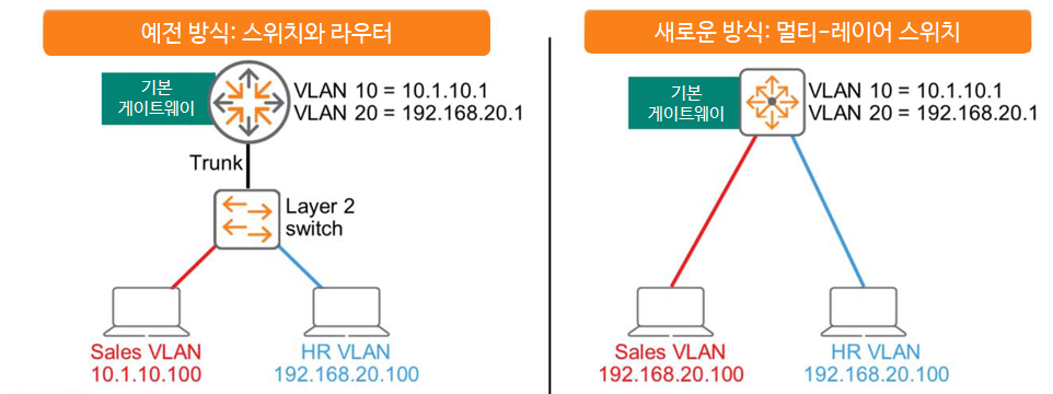
In the past, multi-layer switches didn't exist. Therefore, for host connectivity, a Layer 2 switch, as shown on the left in the figure above, was used, and routing between devices within the switch was only possible through an external router.
A potential problem with this approach is that the Switch-to-Router link can become oversubscribed. While LAGs can mitigate this issue to some extent, they require additional routing decisions to send frames to the router, making them less than optimal.
However, multi-layer switches are different. They efficiently connect switching and routing functions via a high-speed internal backplane. Initial routing decisions and other processes are all performed within the switch box. This reduces latency and improves performance.
All AOS-CX switches are multi-layer switches with routing enabled by default.
IP routing table
Routing devices, such as routers or multi-layer switches, It tells you the best route Routing tableCreate and maintain.
You can manually add entries to the routing table in the form of static routing, or you can configure a routing protocol to automatically create and maintain this table.
Typically, entries in a routing table do not expire unless they are updated due to topology changes.
This is different from the MAC address table, where entries expire and disappear after 5 minutes if the switch stops receiving traffic from the endpoint.
The figure below simply shows an environment where Core-1 and Core-2 routers are connected.
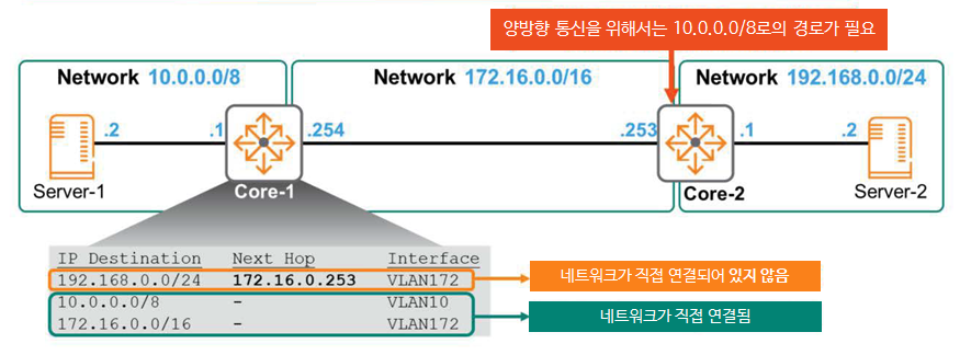
There are three networks: 10.0.0.0/8, 172.16.0.0/16, and 192.168.0.0/24.
Let's take a look at Core-1's routing table here.
The first entry contains the following:.
""To get to the network 192.168.0.0/24, you need to send the packet to the next hop router 172.16.0.253.
Forward packets to local VLAN 172 to reach the next hop address.""
The following two items mean the following:.
""There is no next hop for the network 10.0.0.0/8 band. You are directly connected to that network.
You just need to forward the packet to the local VLAN 10 interface.

The network band 172.16.0.0/16 is also directly connected. Forward packets to the VLAN 172 interface.""
Here, let's assume that routing is configured only on Core-1.
When Server-1 wants to communicate with Server-2, Core-1 must correctly route the packet and send it to Core-2.
Core-2 will send packets to Server-2, which is connected locally, without any problems.
Therefore, one-way communication from Server-1 to Server-2 is successful.
However, when Server-2's response is forwarded to Core-2, Core-2 receives the packet but drops it because the destination (10.0.0.2) is not in its routing table. Bidirectional communication is not possible.
To resolve this issue, you must configure a route in the Core-2 routing table for the 10.0.0.0/8 network, which is not directly connected to Core-2.
VRF (Virtual Routing and Forwarding)
We just learned that we can create and communicate multiple VLANs on a single physical switch.
It's like creating a virtual switch for each VLAN inside a physical switch.
Similarly, you can use the Virtual Routing and Forwarding (VRF) feature to create a separate virtual router within a single physical router.
VRFs are useful in situations where IP addresses overlap across multiple locations on a network.
For example, this could happen when two companies merge.
Alternatively, VRFs can be useful in multi-tenant environments. While customers A, B, and C are physically connected to the same L3 switch, their routing tables operate virtually independently, eliminating the need for ACLs to block communication between customers.
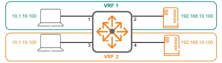
The above diagram shows a single multilayer switch divided into two separate VRFs. Interfaces 1 and 2 belong to VRF 1, while interfaces 3 and 4 belong to VRF 2. The two VRFs do not interact with each other and act as separate, unconnected routers.
Here's how to configure VRF in AOS-CX:.
Switch(config)# vrf <VRF 이름>
Switch(config-vrf)#
To assign an interface to the created VRF, use the attach command.
Switch(config)# interface 1/1/1
Switch(config-if)# vrf attach <VRF 이름>
This is why communication is possible even though the IP addresses are the same. In AOS-CX, all interfaces are mapped to a global VRF called default by default. In other words, all interfaces are part of the same VRF.
Physical routers and global VRFs are essentially the same.
If you decide to partition the network by creating VRFs 1 and 2, as in the example above, the two VRFs will not communicate with each other by default. However, you can configure the solution to route between the two VRFs if necessary.
Additionally, AOS-CX also includes a VRF called mgmt for management purposes. This is available only on Out-of-Band Management (OOBM) ports.
We have learned about the types of interfaces required for routing and routing tables.
Okay, now let's take a look at how packets are actually transmitted.
Packet Delivery Process
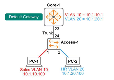
In the diagram above, PC-1 and PC-2 need to communicate with each other. Both endpoints are connected to the same Layer 2 switch, Access-1, but are mapped to different VLANs. The Core-1 multi-layer switch performs inter-VLAN routing. The default gateway for VLAN 10 is 10.1.10.1, and the default gateway for VLAN 20 is 10.1.20.1.
※reference: As mentioned earlier, deploying Layer 2 access services and Layer 3 routing services on a single multilayer switch improves efficiency. However, large-scale networks typically have a separate access switch for endpoint connections, which is connected to an L2/L3 multilayer switch.
This design is easy to expand.
So, let's see how packets are transmitted according to the scenario.
1. Forward packets from endpoints to access switches
PC-1 generates a message containing the following information:.
- Layer 3 header: Source (PC-1) IP – 10.1.10.100 / Destination (PC-2) IP – 10.1.20.100
- Layer 2 header: Source (PC-1) MAC address / Destination (default gateway – 10.1.10.1) MAC address
If PC-1 does not yet know the MAC address of 10.1.10.1, it obtains the MAC address information through the ARP process.
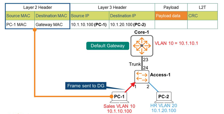
2. Packet forwarding from the access switch to the multi-layer switch
Access-1 receives the frame and checks the destination MAC address in Layer 2.
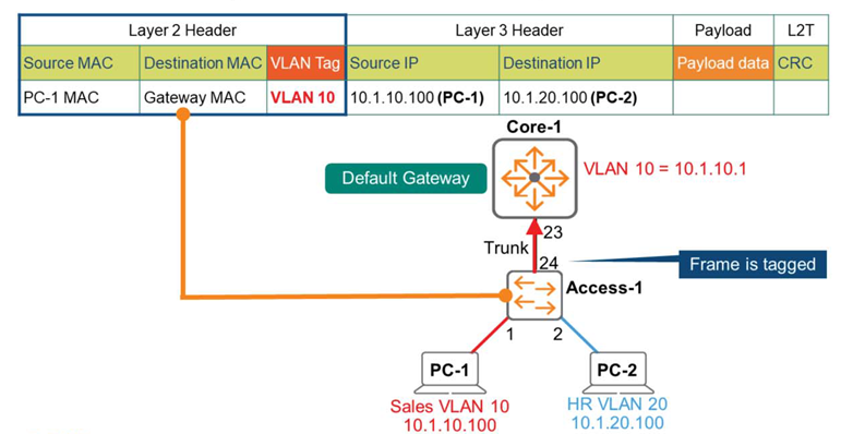
Find a matching entry in the MAC address table and determine that this frame should be forwarded to Core-1 via the Trunk Link (port 24). Add an 802.1q tag, VLAN = 10, and forward the frame to Core-1.
3. Routing Process
Core-1, a multi-layer switch, is the Layer 2 destination for this frame.
It accepts the frame, strips off the Layer 2 header, and begins performing routing functions to check the Layer 3 header information.
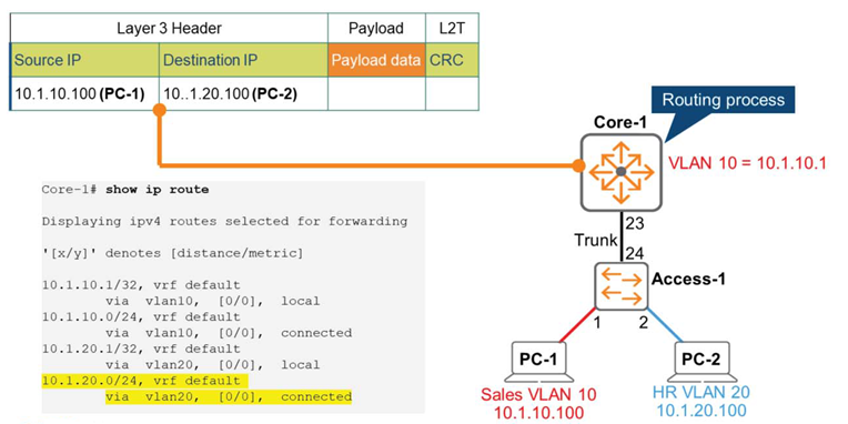
Compare the Layer 3 destination IP address with the routing table information on Core-1. As shown in the figure above, Core-1's routing table shows that the 10.1.20.0/24 network is directly connected to the Switch Virtual Interface (SVI) VLAN 20. Therefore, the Core-1 switch forwards the packet to the VLAN 20 interface.
4. Packet forwarding from multi-layer switch to access switch
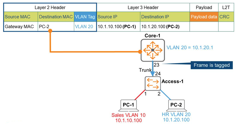
The Core-1 switch wraps a new frame around the IP packet. This frame contains an 802.1q tag and VLAN = 20.
Now we forward this frame to Access-1, which is an L2 switch.
5. Forwarding packets from the access switch to the endpoint
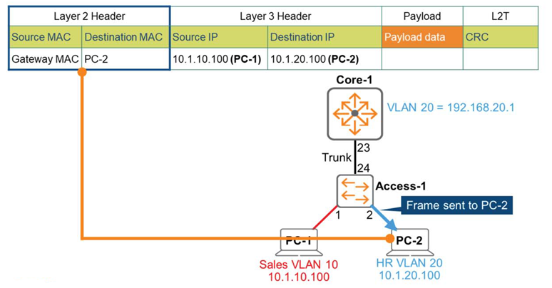
Switch Access-1 receives the frame and determines that it's VLAN 20 based on the tag. 802.1q is removed, having served its purpose. Switch Access-1 compares the destination MAC address with its own MAC address table.
Finds a match and forwards the frame to PC-2 on port 2.
Well, this is the end of this long story.
As we move from Layer 2 to Layer 3, we see why switches perform routing functions and how they work.
In the next post, we'll take a closer look at Layer 3 operations while learning about VRRP and routing protocols.