In the last post, we briefly looked at LAG (Link Aggregation Group).
LAG has two operating modes: Static LAG and Dynamic LAG.
Then let's take a look at them one by one.
Static LAG
In Static Link Aggregation mode, no control information is exchanged between devices. In other words, no LAG-related signals are exchanged between switch peers. Simply configure the link aggregation (LAG) independently on each peer. Once configured properly, the LAG will be operational.
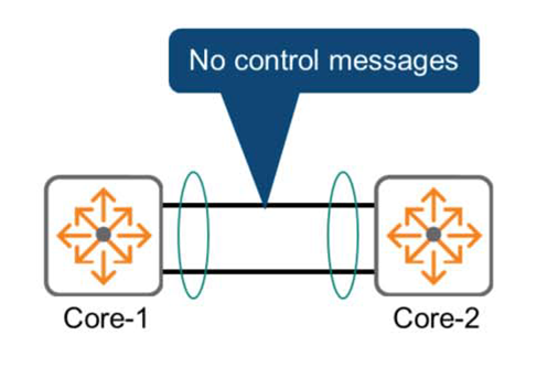
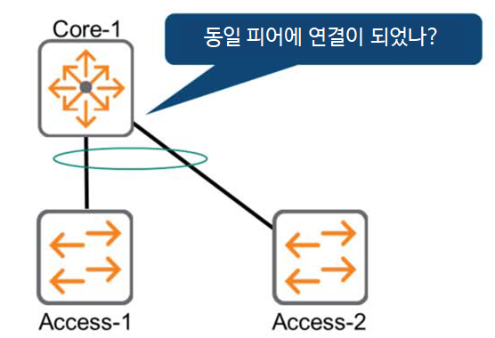
However, each switch does not know who it is connected to or whether it is connected to the same peer.
Because even if one side misconfigures, it is not detected by the peer. This mod is not recommended.
This may result in unexpected behavior and may be difficult to detect or troubleshoot.
If you look at the figure below, you can see that the Core-1 switch is not detecting that the LAG member ports are connected to different peer switches.
Static LAG configuration
Here's how to configure Layer 2 Static LAG on an AOS-CX switch:.
1. First, create a LAG interface. Create it with an ID number that identifies the interface. The ID can be set from 1 to 256.
Switch(config)# interface lag <id>2. Disable routing functionality for the new LAG interface.
Switch(config-lag-if)# no routing3. Map the physical interface ports to member ports of the LAG.
Switch(config)# interface {member/slot/port}
Switch(config-if)# lag <id>
By performing the same operation on each switch, the LAG configuration between the two switches is complete.
Let's take a look at an example of a LAG configuration between the following two switches.
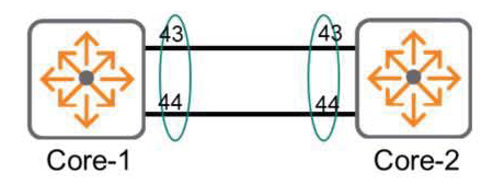
Core-1(config)# interface lag 20
Core-1(config-lag-if)# no routing
Core-1(config)# interface 1/1/43
Core-1(config-if)# lag 20
Core-1(config)# interface 1/1/44
Core-1(config-if)# lag 20
Core-2(config)# interface lag 20
Core-2(config-lag-if)# no routing
Core-2(config)# interface 1/1/43
Core-2(config-if)# lag 20
Core-2(config)# interface 1/1/44
Core-2(config-if)# lag 20802.3ad – Dynamic LAG
In the 802.3ad standard, peer devices using Dynamic LAG exchange control messages to establish and maintain the LAG. This mechanism detects link failures and ensures that LAG member ports are configured on the same device.
This standard is generally Link Aggregation Control Protocol (LACP)LACP periodically exchanges messages called LACP Data Units. These messages contain:.
- System ID: Switch identifier
- Operational Key: LAG (Link Aggregation Group) identifier
Additionally, LACP-DU (LACP Data Unit) contains several flags as follows:.
- LACP_Activity
- LACP_Timeout
- Aggregate
- Synchronization
- Collecting
- Distributing
To avoid unexpected network problems: It is recommended to apply link aggregation with Dynamic LAG or LACP.do.
The 802.3ad standard allows for up to 16 ports to be combined, but only 8 ports can be used simultaneously.
802.3ad operating mode
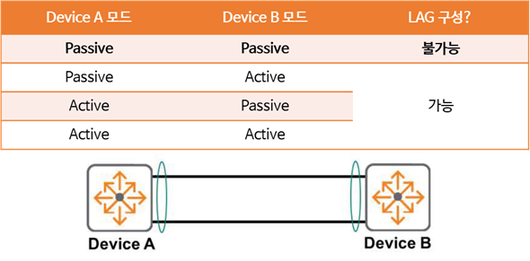
LACP can be configured in one of two modes:.
Passive modeIn , the device waits until it receives an LACP Data Unit (LACP-DU) message from another peer to automatically create a Link Aggregation Group (LAG). This mode leaves the LAG in the listening state. Like, “I have to sit here and wait until I hear from my peers.”As such, if the other peer switch is also configured in passive mode, both switches will think the same way: they will sit and wait for someone else to send a message, preventing the LAG connection and configuration from taking place.
That is, at least one peer must be in Active mode.
Active modeIn , the device itself sends LACP Data Unit messages through the member ports. “Let’s form a LAG!!”This means that the peer responds to the message and continues negotiation, regardless of whether it's in passive or active mode. Ultimately, the LAG is successfully established.
Okay, so let's see how to configure it on the AOS-CX switch.
How to configure Dynamic LAG
Configuring a Dynamic LAG is similar to configuring a Static LAG, except that a command is added to select the LACP mode.
Switch(config-lag-if)# lacp mode {active | passive}Let's take a look at an example of configuring Dynamic LAG on a switch as shown below.
Core-1(config)# interface lag 20
Core-1(config-lag-if)# no routing
Core-1(config-lag-if)# lacp mode active
Core-1(config)# interface 1/1/43
Core-1(config-if)# lag 20
Core-1(config)# interface 1/1/44
Core-1(config-if)# lag 20
Core-2(config)# interface lag 20
Core-2(config-lag-if)# no routing
Core-2(config-lag-if)# lacp mode active
Core-2(config)# interface 1/1/43
Core-2(config-if)# lag 20
Core-2(config)# interface 1/1/44
Core-2(config-if)# lag 20Check the LAG interface
“You can check the configuration using the ”show interface lag” command.
Switch# show interface lag Aggregate lag1 is up Admin state is up Description : MAC Address : 88:3a:30:97:59:c0 Aggregated-interfaces : 1/1/25 1/1/26 2/1/25 2/1/26
 Aggregation-key : 1 Aggregation-mode : active Speed : 40000 Mb/s
 L3 Counters: Rx Disabled, Tx Disabled <<< >>>
Additionally, you can check the total available bandwidth of the LAG via “show interface lag brief”.
Switch# show interface lag brief
------------------------------------------------------------------------------ Port Native Mode Type Enabled Status Reason Speed VLAN (Mb/s) ------------------------------------------------------------------------------ lag1 1 trunk -- yes up --              40000
Load Sharing
When configuring a LAG, each peer device must coordinate traffic load balancing across its member ports (physical interfaces). The switch uses a hash algorithm to determine which member port to use for a given packet.
A hash algorithm is a mathematical function applied to an input value (x). The output value (y) alone cannot be used to predict or infer the input value (x). It is also called a one-way function. Another characteristic of a hash is that the output value (y) is always the same for the same input value (x).
The switch uses packet header information as input (x) to a hash algorithm, and the output (y) is the member port to use for that specific packet. Depending on the switch algorithm used, the hash input can be:.
- Layer 4 TCP/UDP ports
- Layer 3 source and destination IP addresses
- Layer 2 source and destination MAC addresses
The following figure shows how Layer 2 source and destination MAC addresses are used as input values for the algorithm.
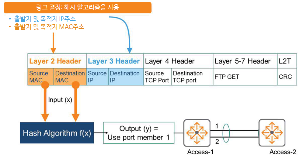
Always use physical port 1 as the output value for all packets with that source and destination MAC address combination. If there is a link problem, these packets will use physical port 2.
AOS-CX switches use source and destination IP addresses as inputs to the hash algorithm by default.
“You can check this using the ”show lacp aggregates” command.
Switch# show lacp aggregates
Aggregate Time: lag1 Interfaces: 2/1/26 1/1/25 2/1/25 1/1/26 Heartbeat rate: Fast Hash: l3-src-dst
Aggregate mode: Active
In the Hash information, “l3-src-dst” is the default, which means Layer 3, i.e. IP address.
However, using a hash algorithm based on source and destination IP addresses may not always be appropriate. It may not distribute the load equally and appropriately across member ports. This can lead to traffic congestion and overall performance degradation.
In this case, you can modify the input values. As shown below, you can use the Layer 2 source and destination MAC addresses as input values for the hash function. This will prevent oversubscription of member ports.
Switch(config)# interface lag <ID>
Switch(config-lag-if)# hash l2-src-dst
So, we've learned about link aggregation.
Link aggregation is a technology used not only between switches but also between servers, storage devices, and routers, so it is important to know the exact commands to configure and verify it.