LAN and VLAN
A Local Area Network (LAN) refers to a group of devices in the same broadcast domain.
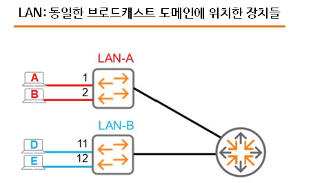
As shown in the figure, there are LAN-A and LAN-B. Two devices are connected to LAN-A.
Host A is connected to Port 1, and Host B is connected to Port 2.
The other switch LAN-B has a similar configuration.
When a switch receives a broadcast message on a random port, it forwards the broadcast to all ports except the port that sent it (flooding). Therefore, when Host A sends a broadcast, the LAN-A switch forwards the broadcast to all other ports. However, Host D and Host E do not receive this frame.
How can we connect these physically separate switches and LANs into a single internetwork? Adding a router capable of routing unicast and multicast traffic between the LANs would be a simple solution.
So, let's take a look at a virtual LAN (VLAN), which functions like a physical LAN.
SW1Let's say we have an Aruba switch called .
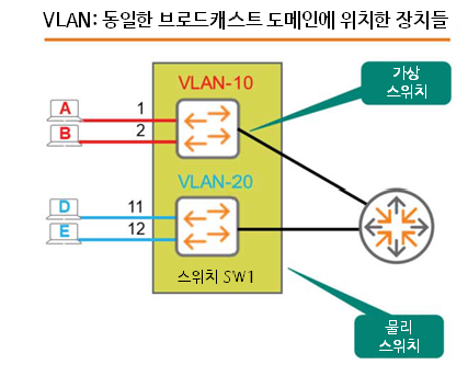
Hosts A, B, D, and E are connected to Ports 1, 2, 11, and 12 of SW1, respectively.
By default, if you don't configure anything, all these devices will be in the same broadcast domain.
When Host A sends a broadcast message, all three remaining hosts receive the broadcast message.
Here “VLAN10”called Virtual LANLet's assume we created .
Inside the physical switch Created a small virtual switchIt is the same as .
This virtual switch exists inside the switch, but is not connected to a physical port.
Therefore, we need to physically define or map Port 1 and Port 2 of SW1 as members of VLAN 10.
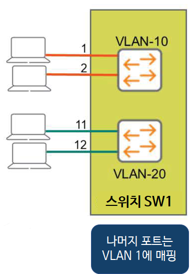
Similarly, create VLAN20 and assign Port 11 and Port 12 as members of VLAN 20.
Okay, I've created two separate broadcast domains on one physical switch – VLAN-10 / VLAN-20
Now, when Host A sends a broadcast, the switch forwards the frame to all ports in the same VLAN except the ingress port. This means that only Host B receives the broadcast. We've effectively recreated the same scenario using a single physical switch.
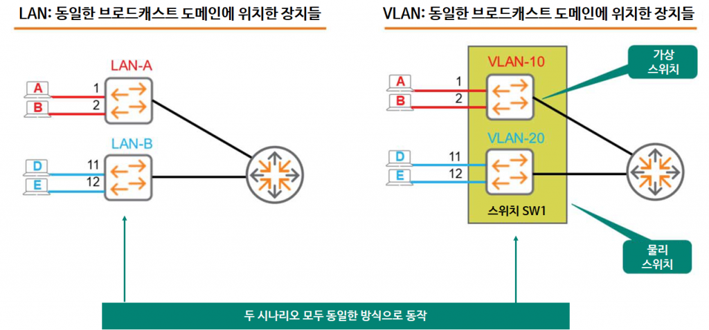
As with the physical configuration, there is no connection between VLANs.
That is, neither unicast, multicast, nor broadcast traffic is passed between VLANs.
Of course, you can create an internetwork by connecting routers, just like in the physical switch scenario.
Well, if it works the same way, why bother using VLANs?
Now let's look at how to configure VLANs along with their advantages.
Create VLAN
The AOS-CX switch identifies VLANs by VLAN ID. The VLAN ID is a number between 1 and 4094.
By default, VLAN 1 is created and cannot be removed. All ports are mapped to VLAN 1.
This is the general default for most switches, not just the AOS-CX switches.
VLAN Commands and Syntax
Create and enable VLANs using the VLAN command.
- The following is an example of creating VLAN 10.
SW1(config)# vlan 10
SW1(config-vlan-10)#- You can create multiple VLANs at once with a single command.
SW1(config)# vlan 2-5, 10- If you are no longer using VLANs, no command나 shutdown commandYou can remove it through .
SW1(config)# no vlan 10SW1(config)# vlan 10
SW1(config-vlan-10)# shutdown- Naming VLANs using the name command is a good practice for administrative purposes.
SW1(config)# vlan 10
SW1(config-vlan-10)# name Sales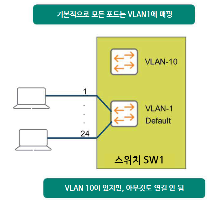
It's important to note that creating VLAN 10 using the VLAN command essentially creates a virtual switch within the physical switch. Even though you've created the VLAN, you haven't yet specified its members.
This means that no devices are connected to this virtual switch.
Access Port
Now, let's create a VLAN and specify its members.
Define VLAN
First, let's create VLAN 10 named Sales and VLAN 20 named Service.
SW1(config)# vlan 10
SW1(config)-vlan-10)# name Sales
SW1(config)-vlan-10)# exit
SW1(config)# vlan 20
SW1(config)-vlan-20)# name Service
SW1(config)-vlan-20)# exit
Mapping ports to VLANs
You can specify interface scopes at once in the global configuration context.
We will map ports 1/1/1 through 1/1/2 to VLAN 10, and ports 1/1/11 through 1/1/12 to VLAN 20.
SW1(config)# interface 1/1/1-1/1/2
SW1(config-if-<1/1/1/-1/1/2)# vlan access 10
SW1(config-if-<1/1/1/-1/1/2)# exit
SW1(config)# interface 1/1/11-1/1/12
SW1(config-if-<1/1/11/-1/1/12)# vlan access 20
SW1(config-if-<1/1/11/-1/1/12)# exit
Here Only one VLAN ID can be assigned to an interface.It is important to remember that.
That is, interface 1/1/1 cannot be a member of both VLAN 10 and VLAN 20. This would be like attending a sales meeting and a technical meeting at the same time.
Check VLAN
You can check the created VLAN and the mapped port using the show command.
SW1# show vlan
---------------------------------------------------------------- VLAN Name Status Reason Type Interfaces ---------------------------------------------------------------- 1 DEFAULT_VLAN_1 up ok default
10 Sales up ok static 1/1/1-1/1/2 20 Service up ok static 1/1/11-1/1/12
In the next post, we will learn about 802.1q trunk ports.