In the mid-1980s, as computers were rapidly advancing, every manufacturer tried to implement their own proprietary communications protocol.
As a result, communication was not properly established, with compatibility issues occurring between products from different manufacturers.
So, the International Organization for Standardization (ISO) solved this problem by proposing the Open Systems Interconnection (OSI) model, a standard communication model for computing devices.
The OSI model is divided into seven layers, and each layer defines a step.
Layer 1: Physical Layer
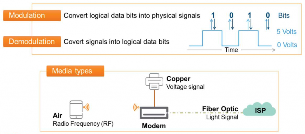
Layer 1 represents the physical devices that transmit and receive signals between two media.
For example, it's easy to think about the router you use at home.
The tablets and smartphones we have connect to our router using radio frequency (RF) signals that travel across the air.
This router connects to an Internet Service Provider (ISP) network, such as KT, SK Broadband, or LGU, using an optical cable coming into your home. The router then converts the data into an optical signal.
Additionally, the printer is connected directly to the router via a cable commonly referred to as a LAN cable, called UTP.
Before a print job is sent to the printer, it is converted into an electrical signal.
The components that convert and transmit logical data into light or electrical signals to convey messages to other media represent the physical layer.
Layer 2: Data Link Layer
Data Link provides three main functions:.
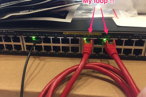
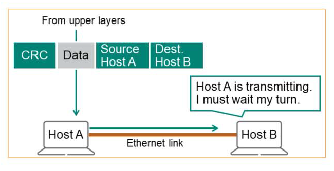
1. MAC (Media Access Control) – Typically, when we have a conversation, one person speaks while the other person listens quietly. Similarly, most media only allows one device to transmit at a time, so access to the media must be controlled.
Before transmitting data, we must utilize the “Carrier Sense” mechanism to detect whether someone is transmitting data, and if a transmission signal is detected, we must wait until the transmission is completed.
2. Link Layer Addressing – In a crowded classroom, if you want to talk to a student named A who's far away, you'll have to call out loudly unless you approach him directly. Others will be able to hear you, but only A will respond.
Likewise, each station on a LAN has a unique name, identified by a 6-byte hexadecimal number called the MAC address. All stations receive messages, but only the intended recipient processes and responds to them. All others simply ignore the message.
3. Error Detection – Layer 2 detects errors that may occur during Layer 1 transmission. This prevents unnecessary processing of corrupted or incomplete messages. This is accomplished by adding a "trailer" to the data.
Layer 3: Network Layer
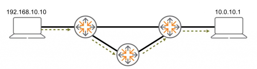
At the network layer, the main goal is to establish communication between multiple LANs or WANs using the best path.
1. Logical addressing – Unique identifiers for origin and destination are used throughout the route.
2. Search and select a route – It selects the best path from all paths found through algorithms and protocols.
The path used to communicate between two devices may not be used later.
The protocols and algorithms used at this layer can update the path at any time depending on several factors.
It's like when we drive with a navigation system, even if we go to the same destination, the route may be different depending on the road conditions or traffic flow.
Layer 4: Transport Layer
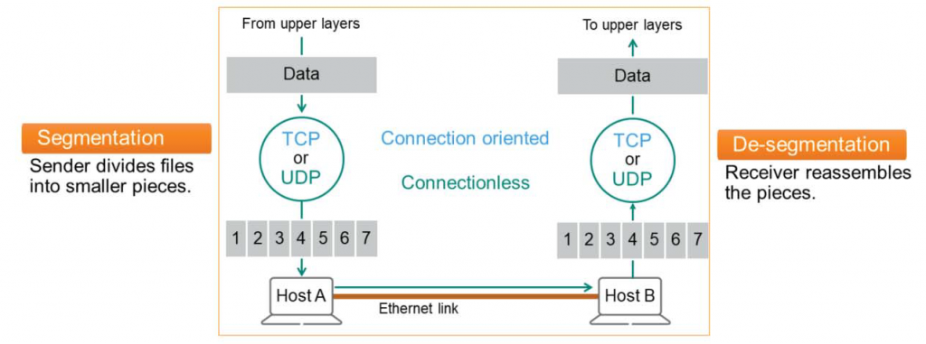
The 4-layer transport layer controls the reliability of the link through segmentation, de-segmentation, and error control.
At this layer, some protocols, such as Transmission Control Protocol (TCP), are connection-oriented. This means that the transport layer can track messages and retransmit failed ones.
Protocols like UDP (User Datagram Protocol) are stateless or connectionless. This means the transport layer doesn't keep track of messages, which has the advantage of making connections relatively quick and easy to compute.
The transport layer has three main tasks:.
- Segmentation – The sender's TCP or UDP process receives the file from each application and breaks it into small pieces (typically 1,500 bytes). Each piece is passed to the lower layer and transmitted individually over the final Ethernet link.
- De-segmentation – The receiving device accepts each segment piece and, if necessary, rearranges it into the correct order and reassembles the information.
- Error Detection – Validate received information to prevent errors that may occur in lower layers (layers 1-3).
※ Error detection is a process that occurs at layers 2, 4, and 7 of the OSI model.
Layer 5: Session Layer
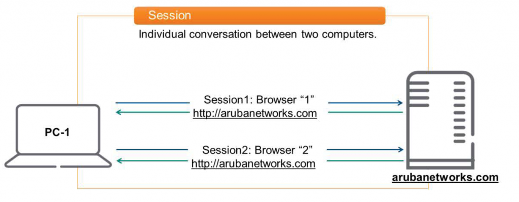
Layer 5 is responsible for establishing, maintaining, and tearing down sessions between two computing devices.
Here, a session means a special conversation between two devices.
For example, open your browser and https://www.arubanetworks.com Assuming you connect to a webpage like this, a session is created. Similarly, if you open another browser and connect to the same website, a different session is created because the application is different. In other words, two separate sessions are maintained.
You can also connect to another computer for file transfer purposes or remotely to work with an Aruba switch. Each creates a separate session.
Typically, a single computer can create thousands of sessions.
Layer 6: Presentation Layer
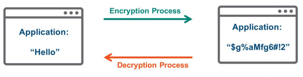
The presentation layer transforms data into a format acceptable to the application. The general process is as follows:.
- Compress / Decompress
- Encryption / Decryption
- Code conversion (e.g. from EBCDIC to ASCII)
For example, an application might send a message like "Hello" to the Layer 6 presentation layer to encrypt it before transmission. Because it's encrypted, even if an unauthorized user, such as a hacker, intercepts the data, it becomes unreadable. Only the intended recipient possesses the digital key to decrypt it.
Layer 7: Application Layer
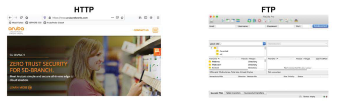
The application layer is closest to the user.
The OSI application layer interacts directly with software programs and users. It provides network resources, providing network services to many user applications, such as file transfer, email, and video conferencing.
Encapsulation / Decapsulation
In this way, each of the seven OSI layers has its own role and communicates between devices on the network according to pre-determined rules. Each device uses a header to control information about a specific layer or higher.
Headers generated at a specific layer of the Sender can only be read at the same layer of the Receiver.
The process of adding headers at each OSI layer is called encapsulation. This process is always performed by the sender's device.
And when a header is added and transmitted, the receiver reads and interprets the header information. This is called decapsulation.