In the last post, we learned about the architecture of the AOS 8 operating system.
As wireless network infrastructure becomes more active and widespread, its stability and performance are becoming increasingly important.
In particular, there is a growing trend of companies adopting Digital Workspace and Mobile Office, which use Wi-Fi instead of the existing wired LAN for business purposes.
If so, the operating system of wireless networks must also change to keep pace with these changes and trends.
More stable and innovative features are needed.
So, in today’s post, we’ll take a look at the special features of AOS 8.
LSM (Loadable Service Module)
Loadable Service Modules (LSM) provide an infrastructure that allows users to dynamically upgrade or downgrade individual service modules without rebooting the entire system. Each service is delivered as a separate package containing the version and instructions for loading and running the service.
Each service module has its own service package, which can be downloaded from the Aruba Support site and installed on the Mobility Conductor (Mobility Master).
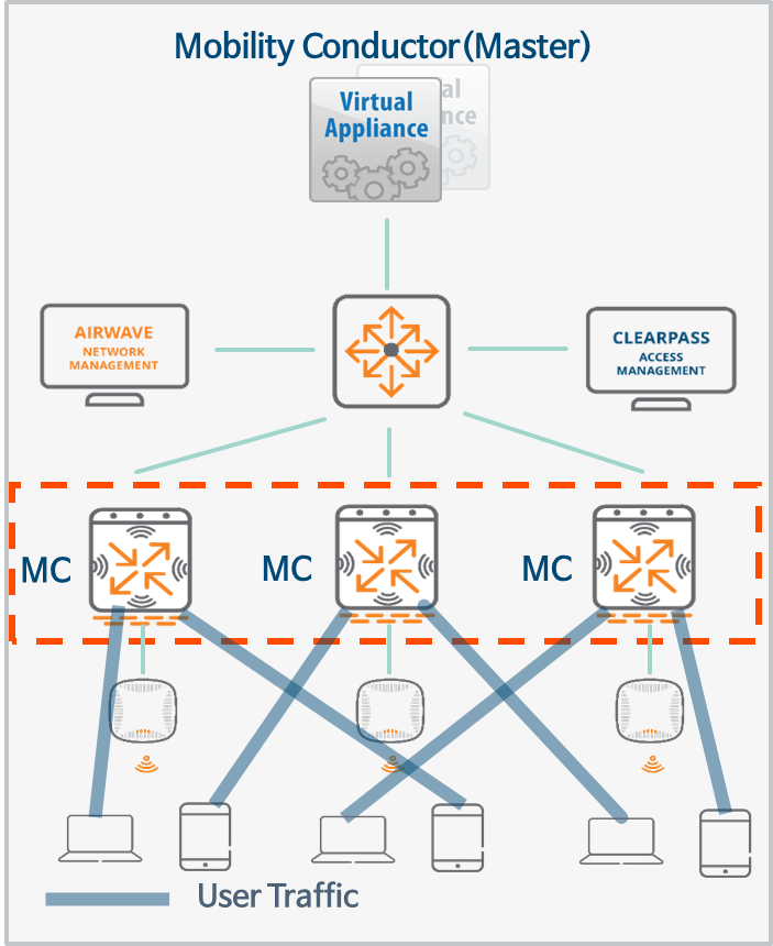
Clustering
Clustering is a combination of multiple devices that provides high availability to all clients and ensures service continuity when failover occurs.
ArubaOS 8.x supports clustering of up to 12 nodes for the 7200 Series Controllers.
Each managed device, i.e., a member of the cluster, can be configured as either L2-Connected or L3-Connected, and even a mixed configuration is possible. However, clients connected to a managed device configured as L3 within the cluster will be deauthenticated.
The cluster supports 7200 series, 7000 series, and VM platform controllers.
- 7200 Series Controller – Up to 12 unitsSupport up to node
- 7000 Series Control – Up to 4 unitsSupport up to node
- 9004 Controller – Up to 4 unitsSupport up to node
- 9012 Controller – Up to 4 unitsSupport up to node
- Virtual Appliance – Up to 4 unitsSupport up to node
Clustering configurations can form a single cluster across different platforms, such as mixing 7200 series and 7000 series controllers. However, mixing virtual appliances and hardware platforms is not supported.
To reduce excessive workload between Management Devices (MDs), the intra-cluster load balancing feature supports station balancing across multiple User Anchor Controllers (UACs).
MultiZone
The MultiZone feature allows you to configure network segmentation using APs. This means that APs can tunnel to controllers (MDs) in different zones. Each zone is a collection of management devices (MDs) located within a single management domain.
This feature allows you to configure a MultiZone AP that can manage multiple zones. Each zone can have a different configuration or architecture. Since each zone is completely isolated, management devices (MDs) between zones do not communicate with each other.
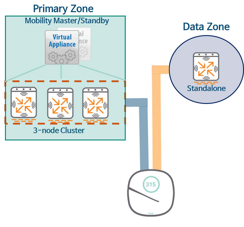
In the picture above Primary Zoneis the area that the AP first connects to when it first boots up. Data ZoneThe AP connects after receiving the MultiZone configuration from the primary zone. Secondary Zoneno see.
SD-Branch
Aruba's SD-Branch is a full-stack solution that monitors and manages all SD-Branch devices, including Aruba's switches, Instant APs (IAPs), and Branch Gateways for each branch's network infrastructure.
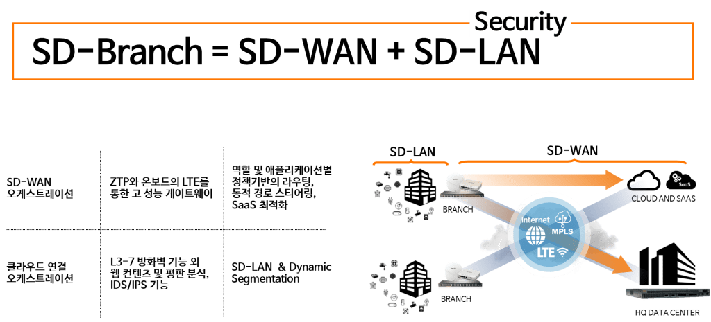
SD-Branch allows you to configure an SD-WAN environment using a broadband Internet connection such as DSL or various types of WAN uplinks such as MPLS.
It also helps improve security at each branch with features such as Role Based Access Control (RBAC), Dynamic Segmentation, and application visibility and control.
Dynamic Segmentation

The Dynamic Segmentation solution is an Aruba feature that assigns policies (roles) to wired ports or wireless sessions based on client access methods. Using Aruba ClearPass Policy Manager, you can add context, such as connection time and device type.
This solution provides the ability to segregate endpoint traffic in a traditional manner via VLANs on the local switch, or by tunneling traffic to an Aruba Mobility Controller.
Dynamic Segmentation supports two types of tunneling methods:.
- User-Based Tunnelling (UBT)
- Port-Based Tunnelling (PBT)
How Dynamic Segmentation Works
All modern devices, including desktop PCs, laptops, tablets, and smartphones, support robust security mechanisms like 802.1x/EAP. However, many devices still don't support these security mechanisms. This is especially true for many IoT devices connected to Power over Ethernet (PoE), such as security cameras, payment card readers, and medical devices.
Security vulnerabilities in these endpoints can pose serious risks to your infrastructure. Switches with Dynamic Segmentation can authenticate these endpoints using ClearPass and tunnel client traffic generated from them to the controller. Tunneled traffic is sent to the Aruba Mobility Controller, allowing central management of firewall functions and other security policies.
This means you can continue to use these IoT devices without risking the security of your network.
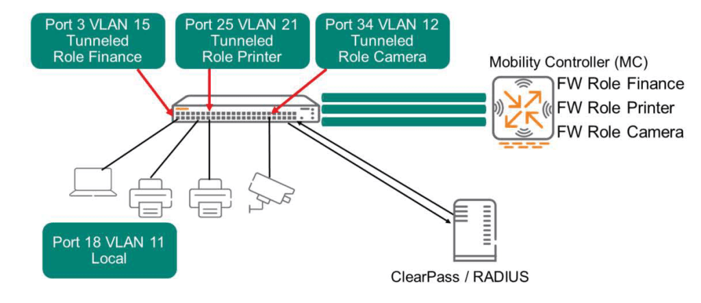
ClearPass profiles each device that connects to the network and considers endpoints that can connect to the network as “allowed.” Approval messagesends a message to the controller. This message includes tunneling information, assigned VLAN, and Secondary role.
ClearPass can also indicate whether a terminal should connect in local mode. The switch will forward traffic to these terminals in the normal manner, without using the tunneling feature to the controller.
Tunneling between controller and AP
The AP creates a GRE tunnel with the controller. All user traffic received by the AP typically arrives encrypted. The AP forwards this traffic directly to the controller through the GRE tunnel. The controller decrypts the encrypted packets, checks firewall policies, and then routes or switches the packets onto the network. For this to work, the user must first be authenticated to the network.
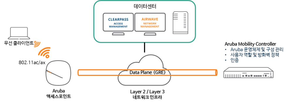
Typically, control traffic uses CPSec, a secure tunnel of the PAPI protocol (UDP 8211), and client traffic is encapsulated in a GRE (Protocol 47) tunnel.
When you configure clustering, APs forward user traffic to the User Anchor Controller (UAC) over GRE tunnels. APs then forward control traffic to the AP Anchor Controller (AAC) over PAPI.
※ reference: The AP does not use GRE to forward user traffic in Bridge mode.
GRE Tunnel
Once the AP receives configuration information from the controller, it must configure GRE tunnels to forward user traffic to the controller. The AP creates one GRE tunnel for each wireless radio and each SSID, plus an additional GRE tunnel for keepalive purposes.
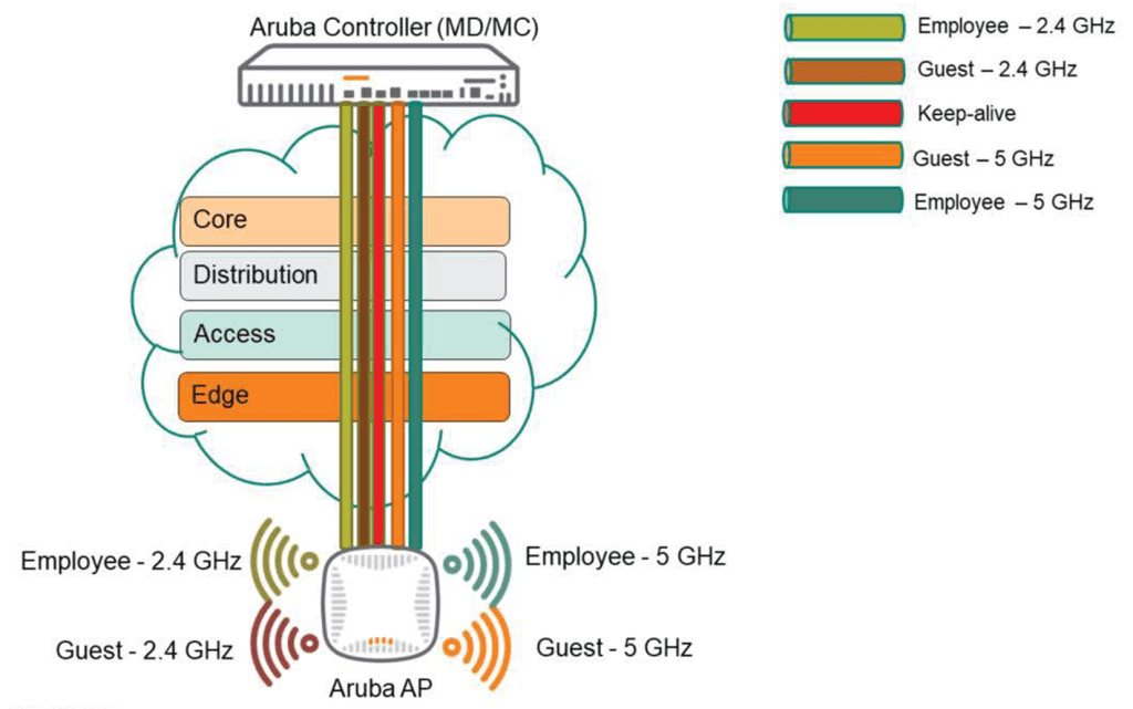
Keepalive tunnels minimize the number of GRE keep-alives generated. Considering a 7240 controller with 2,048 APs, each with three SSIDs, this would result in 2,048 x 6 (2.4Ghz x 3 + 5Ghz x 3) = 12,288 GRE keep-alives generated per second. However, with just one GRE keep-alive tunnel, this number is reduced to 2,048.
We have looked at the features and functions of AOS 8.
So, with these characteristics, let's take a look at how to deploy APs and controllers for each purpose or environment.
Campus AP configuration model

In a campus environment, all APs can be deployed in Campus Mode (CAP) across all buildings and on each floor of those buildings. Aruba recommends powering each AP using PoE and configuring a cluster for AP failover and load balancing.
Additionally, you must plan the configuration of AAC (AP Anchor Controller) and UAC (User Anchor Controller) for load balancing.
Many networks today utilize AirWave or ClearPass servers to provide additional functionality and visibility for security and network monitoring purposes. It's also recommended to have at least one air monitor (AM) on each floor.
Remote AP and VIA configuration models
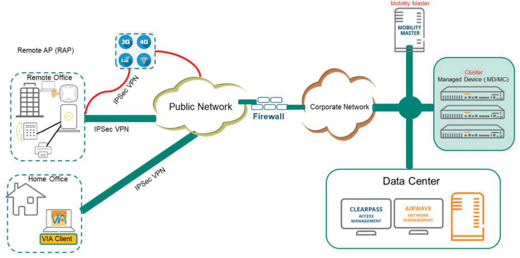
In the RAP (or VIA) model, RAPs can be deployed to provide access (wired and wireless) to the corporate network from remote locations (small) or home offices. For this reason, RAPs are very popular in many networks. They can be installed anywhere with Internet access, including small branch offices or home offices. RAPs can also have a backup uplink using a USB-EVDO/GMS USB stick.
The RAP tunnels to a controller located in the DMZ via an Internet connection, such as at home or in a hotel. Additionally, some customers use the RAP with a USB-EDVO/GSM USB stick to connect to the corporate network while on the move.
VIA is a VPN client that integrates fully with Aruba solutions. VIA is dormant when the client device is on the corporate network, but automatically activates when the client is on an external network.
Most RAP/VIA deployments use "Split Tunnel" mode, which passes only corporate traffic back to the controller, while non-corporate traffic is bridged locally (traffic separation is performed using Split Tunnel firewall policies).
Branch configuration model
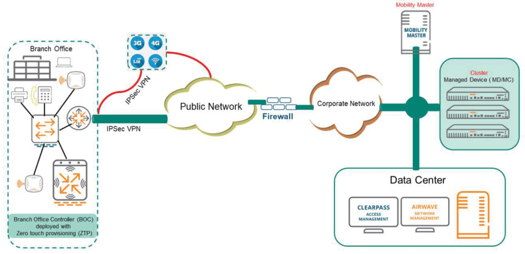
The branch office model is ideal for distributed businesses with branch and remote offices and locations.
Use a cost-effective hybrid WAN connectivity solution with broadband lines like inexpensive DSL and LTE lines.
The 7000/9000 series cloud service controllers are optimized for the following environments:.
- More likely to use cloud security architecture instead of dedicated security appliances
- Clients are more likely to access applications in the cloud rather than on local application servers.
In this model, you can deploy a Branch Office Controller (BOC) using Zero Touch Provisioning (ZTP). When connected to the network, the Managed Device (BOC) establishes a secure tunnel to the master and downloads the global configuration. Zero Touch Provisioning automates the deployment and installation of managed devices in a plug-and-play manner.
AOS 8 also provides features such as “Authentication Survivability” and “WAN Health Check”.
When the remote authentication server is inaccessible, the BOC (Managed Device) can provide Authentication & Authorization Survivability to the client through the Authentication Survivability feature.
The health check feature uses ping probes to measure WAN availability and latency on selected uplinks. Based on the results of this health check, managed devices can either continue using the primary uplink or failover to a backup link.
In this post, we will take a look at the best practices for installation and configuration, including the special features of AOS 8.
Next, we will take a closer look at the types of licenses for AOS wireless environments, their functions, and configuration methods.