To design, implement and configure a more resilient and stable high-performance network, Stacking It requires skill.
In this post, we will learn about this stacking technology and also about the stacking technologies of Aruba switches, namely VSF (Virtual Switching Framework) and VSX (Virtual Switching eXtension).
Operation Plane – Data / Control / Management Plane
Network devices are logically organized into three operational planes, each of which performs a different role.
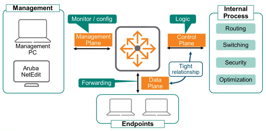
Data Plane
The data plane is much faster than the software. ASIC(Application-Specific Integrated Circuits, custom semiconductors) uses special hardware called a CAN bus to receive and transmit frames.
The ASIC modulates and demodulates data, and handles functions related to frame transmission and reception.
Control Plane
Control plane logic determines what to do with the received data.
These decisions are made through internal processes such as routing, switching, security, and traffic optimization. The data plane and control plane work closely together to process all data as quickly as possible.
Management Plane
You will use the Management Plane to monitor and configure your devices.
This plane must be separated from the data plane for security, access control, and other reasons.
Most network administrators wouldn't want access to devices solely dependent on things like VLANs or VRFs. They need to be able to access devices even if there's a problem with the control or data plane. They also wouldn't want users to have access to the management plane, as this could be a serious security issue.
※ reference: ArubaOS-CX devices are completely isolated from the data plane. OOBM (Out-of-Band Management)A separate interface and VRF are applied for .
Stacking technology
Stacking technology allows multiple physical switch groups to be managed as a single device, called a virtual switch. Control and management plane functions are centralized in a single group member, while each member operates its own independent data plane.
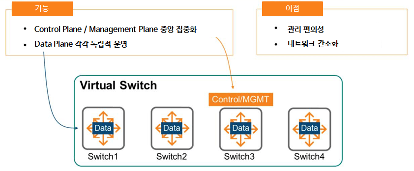
The benefits of utilizing stacking technology are as follows:.
- Ease of management: There's no longer a need to connect, configure, and manage each individual switch. Simply configure the primary switch, and the configuration information will automatically be distributed to all virtual switch members.
This simplifies network setup, operation, and maintenance. - Network Simplification: Because multiple devices share a common control plane, routing protocols and Spanning Tree are not required within a stacking group. Each device within the group perceives itself as a single device.
Distributed Data Plane & Distributed Link Aggregation
Stacking technology maintains a data plane that is distributed across all members.
That is, each physical device individually creates and populates a forwarding table such as ARP and MAC, and this table is shared with all members through the control plane.
Since mobility controllers, firewalls, servers, etc. are aware of Link Aggregation Group (LAG) connections, you can also enable LAG on your switches to take advantage of stacking.
As you can see in the example picture below, even if SW1 fails, traffic can still use other LAG links.
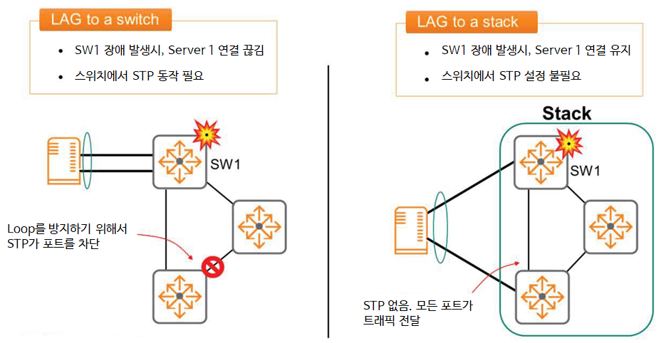
LAG and stacking capabilities allow you to fully utilize all available links in your network simultaneously.
Because a single stack operates on a single control plane, a spanning tree is not required, as previously discussed. Aruba strongly recommends this configuration.
Aruba VSF Stacking Solutions and Platforms
The Aruba Virtual Switching Framework (VSF) configures individual physical switches, interconnected via Ethernet links, into a single virtual switch. All member switches share a single control plane, as previously mentioned, and devices connected to the VSF are perceived as a single device.
VSF in ArubaOS-CX is supported on the 6200F models, including the 6300M and 6300F (as of November 2021).
Other ArubaOS-CX switches use a technology called VSX. The 6300 Switch Series can stack up to 10 members, while the 6200 Switch Series can stack up to 8 members.
This feature Enabled by defaultIt is done.
VSF technology is available on ArubaOS switches, as well as on ArubaOS-CX switches. However, unlike CX switches, it is disabled by default.
VSF functionality is not compatible between ArubaOS-CX and ArubaOS platforms. That is, you cannot configure a VSF stack with switches and models from different OS families.
Roles and Links of VSF Members
As repeatedly explained previously, Aruba VSF creates a single control plane that operates across all members of the stack. This member is the primary member and always uses member ID 1.
This device has the Master (Conductor) role in the stack.
※ reference: ArubaOS-CX switches boot as VSF-enabled switches with default Member ID 1.
This means that the switch acts as a Primary Member.
The Secondary Member provides high availability in the event of a Primary Member failure. You can select a member to perform the Secondary role, but you must explicitly define it. Simply configure any ID value except 1.
The remaining devices in the VSF are members that operate only the data plane and cannot assume the Master (Conductor) role.
To configure a VSF stack, each switch connects to the others using SFP56 or SFP+ ports. Once configured for VSF, the ports can no longer be used as Layer 2 or Layer 3 interfaces. In other words, the VSF ports no longer belong to the data plane.
VSF Open Virtual Switch Database (OVSDB)
In the previous post, I talked about the Current State Database.There is this.
This is the most critical element of the ArubaOS-CX architecture, connecting to all control and management protocols. In the VSF stack, this database runs on the Master (Conductor) switch.
When VSF is configured and running on a switch group, an Open Virtual Switch Database (OVSDB) is also created. This new database runs on the master switch and contains state and configuration data for the VSF stack itself.
The master switch synchronizes the OVSDB contents with the standby (secondary member) to enable rapid transfer of the master role without interruption. The OVSDB database contains six tables:.
- VSF member table
- VSF link table
- System Tables: Number of members, MAD status, fragment status, topology type, etc.
- Subsystem Table: Boot time per member
- Interface Table
- Topology table
VSF topology
VSF members must physically connect the switch stack in either a daisy chain or ring topology.

- Daisy Chain: As the name suggests, this topology connects VSF members in a chain formation using Ethernet connections.
As you can see in the picture above, the stack can be split due to problems between switches or links. - Ring Topology: This topology is recommended because it provides a backup link in case of switch or link failure.
※ reference: Ring topology is not allowed in a stack consisting of two switches.
※ reference: Full Mesh topology is not supported.
VSF Requirements
To configure VSF on an ArubaOS-CX switch, the following requirements must be met:.
- Requires ArubaOS-CX 10.04 or later
- All members must use the same OS-CX version.
- For switches of the same series, stacking configurations are possible by mixing models (i.e. 6300M 48p + 6300M 24p + 6300F 24p, etc.)
- VSF links use regular Ethernet links.
- It is recommended to use uplinks such as 10G, 25G, or 50G.
VSF Member ID and port number
When configuring a VSF stack, all physical switch devices use a single control plane.
This means that you can configure interfaces on any switch using the standard ArubaOS-CX Member/Slot/Port notation, as shown in the figure.

“show interface brief” You can use the command to view port information for all switches in a stack.
※ reference: Since all 6300/6200 switches are fixed switches, the slot number is always fixed to 1.
How to Configure VSF (VSF Configuration Example)
- Access-1 (Master) settings
Access-1(config)# vsf member 1
Access-1(config-vsf)# link 1 1/1/27- Access-2 (Standby) settings
Access-2(config)# vsf member 1
Access-2(config-vsf)# link 1 1/1/27
Access-2(config)# vsf renumber-to 2
Access-2(config)#! Switch reboots- Add Secondary Member
Access-1(config)# vsf secondary-member 2
Access-1(config)#! Switch reboots- Check configuration
Access-1# show vsf
<< >> Mbr Mac Address type Status ID --- ------------------- ------------ --------- 1 88:3a:30:97:c7:00 JL668A Master 2 88:3a:30:97:1a:80 JL668A Standby
VSF Pre-Provisioning
ArubaOS-CX switches support member pre-provisioning.
This feature allows you to provision VSF links and members for a specific switch model before the switch is connected to the stack.
Once the switch is in the stack, it will boot with the appropriate configuration information.
Switch-6300(config-vsf)# vsf member 4
Switch-6300(config-vsf)# type jl658a
Switch-6300(config-vsf)# link 1 1/1/25
Switch-6300(config-vsf)# link 2 1/1/26
Layer 2 Traffic Tracking: Unicast
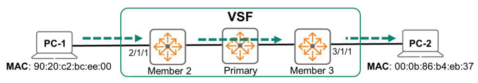
When a VSF member receives a frame for Layer 2 forwarding, it consults the L2 Forwarding Table to determine which interface to forward the frame to. The frame is forwarded to an interface that may be on its own or another member.
If the interface to be sent is on another member, the source member forwards the packet over the VSF link.
A VSF fabric environment is similar to a switch configured with link aggregation.
Learn MAC addresses from logical LAG entities, not physical interfaces. Select one LAG member link to forward each communication.
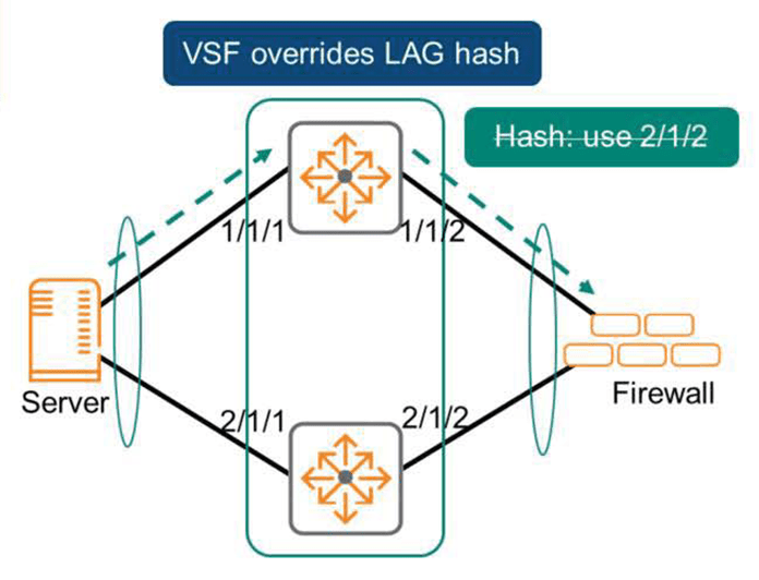
However, VSF does not use the LAG hash function to select the corresponding physical interface.
VSF members prefer to use their own local links rather than VSF links. If a VSF member has multiple local links within an aggregation, a common hashing mechanism is used to select a link.
VSF Failover & OSPF Graceful Restart
The Primary Member is the most important device in the stack and serves as the control and management plane. External devices exchange routing and switching protocols directly with this member.
If something goes wrong with this member and the protocol exchange fails, the entire stack will go down.
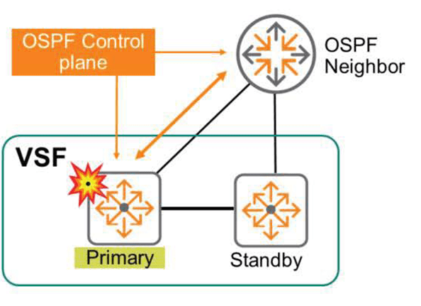
Therefore, for redundancy, a secondary member of VSF must be configured.
The secondary member assumes the master role in the event of a failure of the primary member. The new master runs all control plane protocols, uses the configuration database, and responds to management sessions.

If a primary member fails, Layer 2 traffic continues to flow without interruption. Layer 3 protocols, such as OSPF, notify the peer of a failover event so that it can restart gracefully. This allows OSPF to re-establish adjacencies. During convergence, the switch continues to route traffic based on the last known routing information before the failure. This typically lasts only a few seconds. Once OSPF is fully re-established, it uses a lot of new routing information.
VSF has no preemption. This means that if a failed member rejoins the stack, it will not replace the stack's master but will instead assume a standby role.
VSF link failure
If a VSF link fails, the VSF stack may become fragmented.
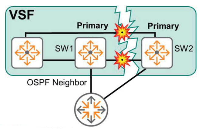
The image above shows a fragmented VSF stack due to a link failure. Originally, SW1 was primary, and SW2 was secondary. However, after fragmentation, there is no direct connection between the two switches. SW1 continues to believe itself to be primary, while SW2, unable to communicate with SW1, now believes itself to be primary.
This condition is called a split-brain condition. The two pieces don't communicate with each other, but they continue to function.
Split brain can cause unstable and unexpected network behavior.
Packets received by one fragment and intended for another fragment are discarded. To make matters worse, since both fragments use the same IP address and routing information, external devices may end up filling in duplicate data.
This causes very strange network behavior.
※ reference: A split-brain condition can also occur if a VSF member fails in the daisy chain protocol.
The best way to resolve a split-brain condition is to disable the ports on one of the pieces. In the figure above, this involves disabling all ports on SW2.
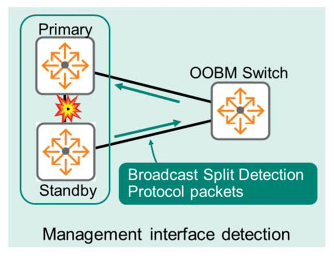
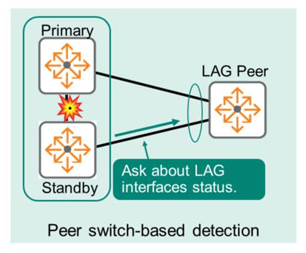
MAD(Multi-active Detection) – Split Detection
Multi-active Detection (MAD) can be used to avoid split-brain situations. This means that if a VSF link fails, the segment containing the standby member checks the status of the primary member. If the original primary member is operating normally, all members of the segment that does not contain the primary member disable all ports.
VSF uses two mechanisms to detect and verify the health of primary members:.
- Management Interface Split Detection: This method requires connecting Out-of-Band Management (OOBM) interfaces to the Primary and Secondary members. These interfaces must all be in the same Layer 2 broadcast domain (VLAN).
This network is used to identify the active stack fragment. Each member broadcasts a split detection protocol packet to identify the currently operating fragment of the stack.
- Peer Switch-based Detection: This method requires no additional connections and relies on the Link Aggregation Group (LAG) implementation. The switch checks the LAG peer for interface status (interfaces connected to the primary and secondary stacks). If the LAG peer determines that the interface connected to the primary member is healthy, the standby member detects a split-brain condition and shuts down the interface.
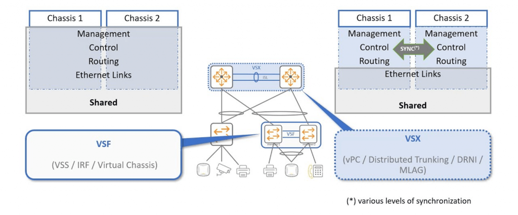
Introduction to VSX (Virtual Switching eXtension)
Aruba VSX is a virtualization technology for ArubaOS-CX switches. It operates on the 8000 Series and 6400 Series switch models. VSX technology is typically applied to data center switches or core switches, while VSF is suitable for access switch models.
VSX improves data plane performance. With VSF, the control plane operates only on the primary member. Therefore, some time is wasted when a non-primary member requests packet processing from the control plane.
However, with VSX, each member runs its own control plane, enabling faster decision making, reduced latency, and improved performance.
Each VSX switch runs a separate control plane, but maintains a database synchronization of its configuration. Unlike VSF, each switch can modify and populate the control plane while appearing as a single virtualized switch to other devices. VSX allows member upgrades with virtually no downtime and continuous packet forwarding.
ArubaOS-CX switches use two virtualization technologies: VSF and VSX.
Depending on the purpose of each switch, models using VSF and models using VSX are distinguished.
Each characteristic is expressed in the figure as follows.
I will cover VSX in more detail in a future ACSP lecture post.