Last time Talking about network redundancyWe also discussed the potential loops that can arise from this. As an alternative, we briefly mentioned Spanning Tree Protocol (STP).
So today, let's take a closer look at the Spanning Tree Protocol.
Spanning Tree Protocol (STP) Overview
STP The standard version of (Spanning Tree Protocol) IEEE 802.1dwas developed to build and maintain a loop-free network while providing a redundant environment. STP eliminates single-path failures while avoiding loops and MAC table instability. STP automatically disables the backup link for redundancy, creating a loop-free topology.
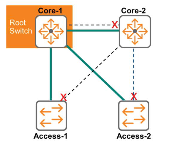
The figure above is an example of an advanced redundant network configuration for resiliency and fault tolerance.
This redundant configuration can lead to loops and related issues. However, with STP, redundant links are automatically disabled. This eliminates potential loop sources in advance, allowing the network to operate without issues like broadcast storms or MAC address table instability.
However, these disabled links will still be used to provide redundancy as needed.
To eliminate these loops and achieve the goal of redundancy, one switch in the STP domain is selected as the Root Switch or Root Bridge. Just as a tree branches out from the ground to its roots, with a single trunk and numerous branches, the Root Switch is designated as the Spanning Switch. TreeIt becomes the root that grows into a tree called .
The remaining switches are called Non-root Bridges or Non-root Switches, and are also sometimes called Designated Switches.
In a loop-free path, it extends from the root to the rest (Non-Root).
※ reference: Today's switches are upgraded versions of the devices previously called "bridges," offering faster speeds and multiple ports. Therefore, the term "bridge" often appears in discussions of STP, and in some contexts, it's perfectly acceptable to use the terms "switch" and "bridge" interchangeably.
STP algorithm
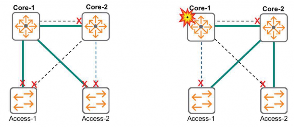
The STP algorithm runs on all switches, and redundant links are activated to prevent loops. However, if a failure occurs, STP converges on the newly activated link's topology and uses it to forward frames. This process maintains a loop-free topology.
※ On the network ConvergeThe term "converge" is interpreted as "all network devices have agreed on a new topological environment," contrary to its original meaning of "converge.".
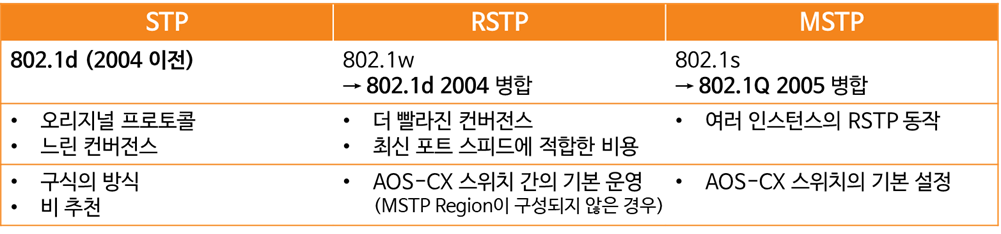
Comparison of STP technologies
STP (Spanning Tree Protocol)
Original standard(IEEE 802.1d) detects failures based on a timer. By default, the root switch generates a “Hello” packet every two seconds. This “Hello” packet is forwarded to all other switches.
If a switch far from the root switch stops receiving "Hello" packets for 20 seconds (the default Max Age Timer), the connection is considered lost, and all switches transition to a new topology environment. The duration of this process is determined by the Forward Delay Timer, which defaults to 15 seconds.
This method is considered very old and outdated and is no longer used in modern network environments.
RSTP (Rapid Spanning Tree Protocol)
RSTP was developed in 1998 to speed up convergence.
Instead of only the root switch generating "Hello" packets, all switches can now do so. This means RSTP now has a mechanism to maintain persistent connections while responding within seconds (or less).
RSTP no longer requires the old and slow Max Age and Forward Delay Timers.
RSTP is backwards compatible with the original standard 802.1d.
However, some of the benefits of RSTP are lost in order to maintain this functionality.
MSTP (Multiple Spanning Tree Protocol)
802.1s or MSTP improves overall protocol performance by implementing multiple loop-free topologies or instances to distribute traffic load across all links. This helps create optimal paths.
AOS-CX switches operate under MSTP by default. However, without any special configuration, they operate like RSTP. The reasons for this behavior will be discussed in detail in the next post.