In the last post, we learned about VLAN.
By creating a virtual switch within a single physical switch, we were able to create and manage broadcast domains more efficiently.
Limitations of VLANs
But, let's take a look at the next picture.
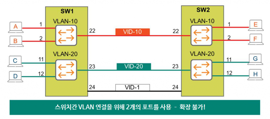
The diagram shows two switches, each with ports configured for VLAN 10 and VLAN 20. Now, to connect these two switches, I'm connecting port 24 on SW1 to port 24 on SW2. Will all terminals on both switches be able to communicate?
Port 24 is mapped to VLAN ID 1, which is the default VLAN. However, because this port is not associated with VLANs 10 and 20, it cannot forward traffic from VLANs 10 and 20.
Only one VLAN ID can be assigned to an interface!
So how can we solve these problems?
A very simple and naive solution is to connect two more links. Connect the two switches by assigning VLAN 10 to port 22 and VLAN 20 to port 23. This will establish a connection between the switches for all VLANs, allowing all terminals on both switches to communicate.
But here's where the problem arises.
What if there are 10 VLANs? 100 VLANs? Interconnecting two switches would require as many physical connections as the number of VLANs. This is not only an unnecessary waste of ports, but it's also virtually impossible.
So we need a way to connect multiple VLANs using a single physical port.
802.1Q Tagging
Let's take a look at the standard Ethernet frame structure below.
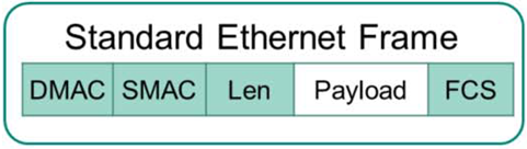
Consider a broadcast frame from Host A that is flooded to all ports assigned to VLAN 10, including port 24. This frame contains no field that would indicate which VLAN the receiving switch is on. Therefore, upon receiving this frame, switch SW2 has no way of knowing whether the broadcast frame is from VLAN 10, VLAN 20, or VLAN 1.
So we need a tagging mechanism that can tell us which VLAN ID it is.
The standard related to this is IEEE 802.1q, which adds an 802.1q Tag field between the Length and Payload fields.
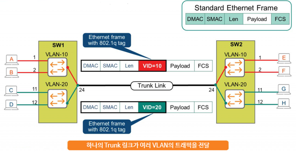
The most important field in this field is, of course, the field called VID or VLAN ID, VLAN Tag.
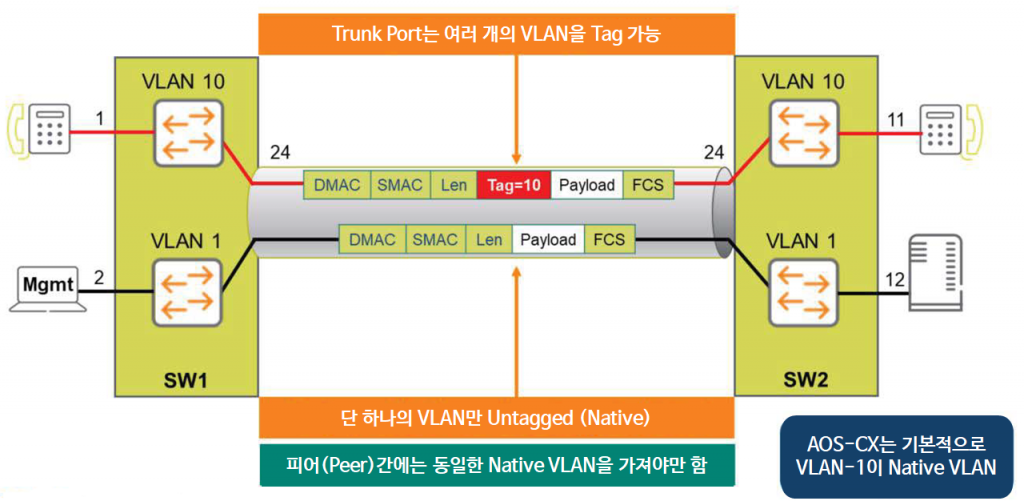
SW1 switch adds this tag to the broadcast frame before sending it out through a port specifically defined as a Trunk Port. When SW2 receives this frame, it sees the tag information and knows that it is traffic from VLAN 10. Then, SW2 removes this special tag and forwards the traffic to all ports in VLAN 10, that is, Host E and Host F.
Likewise, when Host G sends broadcast traffic, it adds a tag of VID=20 to the trunk port, port 24, of SW2 and sends it to SW1. SW1 recognizes that the traffic is from VLAN 20 through the traffic information, removes the tag, and then sends the traffic to Host C and Host D.
So now you can extend the VLAN concept across multiple switches using a single physical port.
The VLAN ID field is 12 bits long, allowing up to 4094 VLAN-IDs to be created. (1-4094)
In the 802.1q standard, administrators can also use frames that do not contain a Tag or VID in the Layer 2 header.
This means that standard Ethernet frames are transmitted without any tags specified.
These VLANs are called Untagged VLANs or Native VLANs.
The default Native VLAN value in AOS-CX is 1, and can be changed with the following command if needed.
SW1(config-if)# vlan trunk nativeIt is recommended to use the same value for the Native VLAN between the two switches (peers).
VLAN Trunk Configuration
On AOS-CX switches, the "vlan trunk" command is used to define allowed VLAN IDs. Multiple VLAN IDs can be assigned to a trunk interface.
SW1(config)# interface 1/1/24
SW1(config-if)# vlan trunk allow 1,10,20
Before configuring a Trunk Port, the configuration for the VLAN must be defined in advance.
Additionally, you can check information about the Trunk interface using the show command as follows:.
SW1# show vlan port 1/1/24

-------------------------------------------------------- VLAN Name Mode Mapping -------------------------------------------------------- 1 DEFAULT_VLAN_1 native-untagged port 10 Sales trunk port 20 Services trunk port
Native VLAN Configuration
As mentioned earlier, all VLAN traffic is tagged to pass through the trunk link, except for the Native VLAN (default: VLAN 1). However, you can change the value of the Native VLAN if necessary.
The example below changes the value of Native VLAN to VLAN 10.
SW1(config)# interface 1/1/24
SW1(config-if)# vlan trunk native 10
Changing the Native VLAN value requires changes to both connected switches. Therefore, when making changes, be sure to ensure that the values are changed on both switches.
You can use the “show lldp neighbor-info” command you learned last time to check which switch is connected to the trunk interface (1/1/24).
“You can check the changed value using the ”show vlan port” command.
SW1# show vlan port 1/1/24 -------------------------------------------------------- VLAN Name Mode Mapping -------------------------------------------------------- 1 DEFAULT_VLAN_1 trunk port
10 Sales native-untagged port
20 Services trunk port