In the last post, we learned what OSPF is and how it works.
So today, let's take a look at what you need to keep in mind to actually operate OSPFv2.
Network type
From a protocol perspective, there are two types of networks:.
- Point-to-point network: Only two peers are present on the link. If the interface is configured as a point-to-point link, OSPF knows that there will be one neighbor on the interface. A PPP serial link would be an example of this type of link.
- Broadcast Network: There may be more than one peer on a link. When an interface is configured as a broadcast network, OSPF recognizes that more than one neighbor device can be discovered on the interface.
In ArubaOS-CX, interfaces are configured as broadcast network type by default, but, “ip ospf network” You can change it using the command.
Switch(config)# interface
Switch(config-if)# ip ospf network {broadcast | point-to-point}
To check the network type you are using: “show ip ospf interface” Use the command.
Unless you actually have multiple routers in the same broadcast domain, it is better to configure the switch-to-switch links as a point-to-point network type.
※ reference: Network type is a concept used when Ethernet was not fully accepted as a unique Layer 2 protocol.
At the time, serial communication was more commonly used, with only one device at each end of the link. This led to the concept of point-to-point networking.
However, Ethernet was designed to allow multiple devices to connect to the same broadcast domain. This ultimately led to the concept of a broadcast network type.
※ reference: OSPF can also use a network type called Non-Broadcast Multiaccess (NBMA). This network can support multiple devices (multi-access), but does not support broadcasting. Frame Relay devices are devices of this type. This type is no longer used in modern network environments.
Scalability issues in broadcast networks
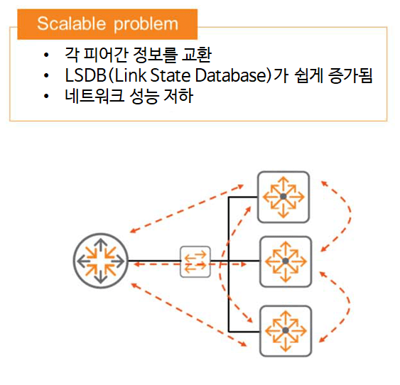
The amount of information that can be exchanged between OSPF peers can be significant in medium-sized or larger enterprise networks.
In broadcast network types, this value can easily increase because each router can have multiple peers. This can impact router performance when hundreds or thousands of routes must be calculated for each OSPF peer. A solution to this problem is therefore needed.
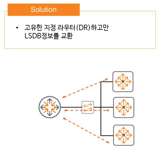
OSPF addresses these scalability issues by selecting a Designated Router (DR) in the broadcast domain. This device maintains full neighbor state with the rest of the devices, meaning that the database is exchanged between peers.
However, unspecified routers do not exchange database information with each other. This helps reduce the amount of information each router in the domain must process.
To maintain high availability, you can designate a Backup Designated Router (BDR) to prevent single points of failure. This device maintains full state along with all devices on the broadcast network. However, it only advertises the primary DR if it fails and is no longer available.
Designated Router (DR) and Backup Designated Router (BDR)
As discussed above, in a broadcast network, an OSPF router is expected to form neighbor relationships with two or more peers. This situation can be potentially extremely inefficient, as LSAs can be flooded and re-flooded in the broadcast domain whenever there's a topology change.
The solution to this problem is to select a designated router (DR), a single point of contact that helps coordinate interactions between peers within the broadcast domain. It will form a full adjacency with all other OSPF peers in the broadcast domain, allowing it to receive and flood LSAs.
In the event of a DR failure, a Backup Designated Router (BDR) takes over. The BDR also maintains full adjacency with the DR and all other peers in the broadcast domain.
The remaining routers that are not selected as DR or BDR are labeled DROTHER. These routers only form full adjacencies with the DR and BDR. This resolves the inefficiency issue mentioned earlier.
Whether there are three routers or thirty routers in the broadcast domain, the DROTHER router only needs to form adjacencies with two peers: the DR and the BDR.
Let's summarize this with a diagram. It might be easier to understand.
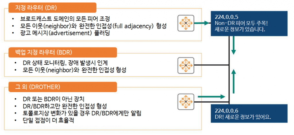
One of the DROTHERs detects a topology change on one of its other interfaces.
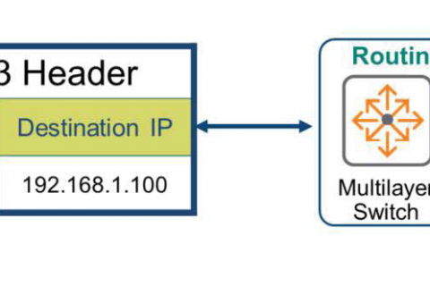
Instead of communicating with every router in the broadcast domain, we only communicate with the DR and BDR. Therefore, we send multicast LSA messages using the destination IP address 224.0.0.6. This IP address is reserved for the purpose of "Attention DR and BDR.".
The DR, operating normally, receives this packet, updates its topology database, and notifies all other non-DRs (DROTHERs) with a multicast LSA message, "Attention all DROTHERs! We have new information!", using the destination address 224.0.0.5.
Selecting a Designated Router (DR)
DR and BDR selection is based on the priority values assigned to the interfaces, with the highest priority value being selected.
In case of a tie, the router with the higher Router-ID becomes the DR.
AOS-CX follows certain rules regarding priority values:.
- The default priority value is 1.
- The range that can be specified for the priority value is from 0 to 255.
- A priority value of 0 means that the router does not participate in DR election.
You can do this configuration at the interface level as follows:.
Switch(config)# interface
Switch(config-if)# ip ospf priority
To check the priority value and selected DR, “show ip ospf interface” or “show ip ospf neighbors” You can use the command.
OSPF Area
In OSPF, an area is a group of OSPF routers that share the same link state database (LSDB).
Every router must be part of some zone.
Segmenting a large network into multiple zones reduces the size of each router's LSDB, lowers CPU utilization, and improves overall network stability. This is because each router in a zone only needs to maintain the topology for its own zone.
For example, in the figure below, SW1, SW2, and SW3 do not need to know about the overall topology; they only need to know about the Area 10 topology.
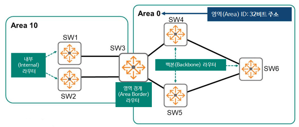
Routers SW1 and SW2 are called "internal routers," and all interfaces are within a single area. When an internal router needs to route packets outside its area, it simply forwards them to an Area Border Router (ABR). An ABR is a router connected to two or more areas. SW3 is an ABR for Area 10, with two interfaces connected to Area 10. It also has two interfaces connected to Area 0.
All areas must be connected to a special backbone area, Area 0. This area is the most critical area in the hierarchy and must be designed with redundancy. Therefore, Area 10 cannot directly connect to any other area other than 0. Communication between two non-backbone areas must be exclusively through Area 0.
A router with interfaces in Area 0 is called a backbone router. In the figure above, SW4, SW5, and SW6 are also internal routers because all their interfaces are in a single area, Area 0. Therefore, they are also called internal backbone routers.
To assign an area to an interface, you must assign an Area ID to the interface. Area IDs are expressed in dot-decimal or decimal notation, similar to a 32-bit IP address. AOS-CX supports both notations.
OSPF LSA Type (LSA 1)
OSPF routers generate various types of Link State Advertisements (LSAs) within the OSPF routing domain, each with a different purpose and scope. Each LSA contains a Link State Identifier (LSA), which describes the network area the router intends to advertise.
Okay, so let's take a look at each LSA type.
The purpose of LSA type 1 is for routers to advertise themselves. Therefore, LSA type 1 is also called a “router LSA.”.
Think of it like we walk into a room and introduce ourselves to people.
""Hello. My name is Rubaruba.""
Similarly, a router introduces itself using LSA Type 1 as follows:.
""Hello, my name is RID 10.1.100.1, I have three active interfaces, and I am participating in this OSPF Area.""
It is important to note that the information shared in LSA Type 1 varies by Link Type.
When different Link Types are configured, you need to consider what information will be shared across server switches.
In addition to defining network types, OSPF also defines two other concepts: Link Type.
Link Type is primarily used to describe an interface or neighbor of an OSPF router.
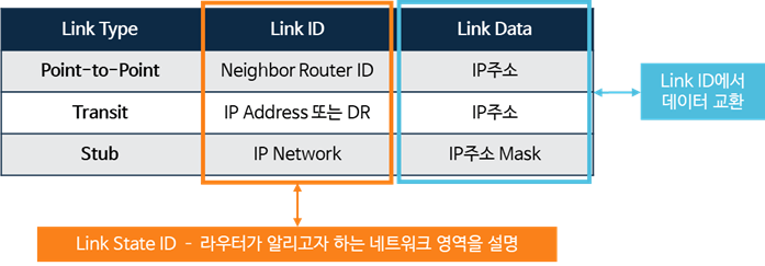
- Stub Link: Used when OSPF is enabled on an interface and the interface has no OSPF neighbors. For example, a loopback interface is considered a stub network.
- Transit Link: Used in broadcast networks with two or more OSPF neighbors.
- Point-to-Point Link: A link used in a point-to-point network, which must have only one OSPF Neighbor entry.
※ reference: Link Type is the result of setting the network ID and the number of neighbors on the link.
For example, if your network type is point-to-point, you know there's only one router on the link.
Otherwise, if the network type is set to Broadcast, the Stub or Transit Link Type is used. If there are no neighbors, the Stub Link Type is used, and if there are one or more neighbors, the Transit Link Type is used.
In AOS-CX “show ip ospf lsdb”You can check the information using the command.
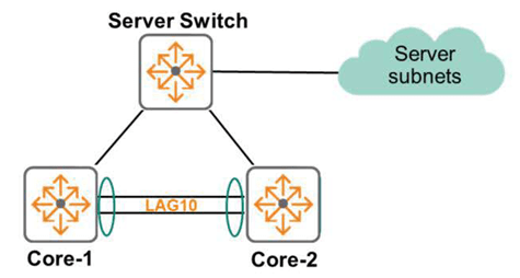
In the topology diagram above, you can see that the Core-1 switch has three routers in its area. This can be used later as a powerful troubleshooting command.
If your network diagram shows five routers, but the actual command shows only three, you'll know right away that there's a problem.
Example of LSA Type 1 message analysis
Now, let's check the information shared in the LSA Type 1 Advertisement of the Server Switch when it is configured with different Link Types.
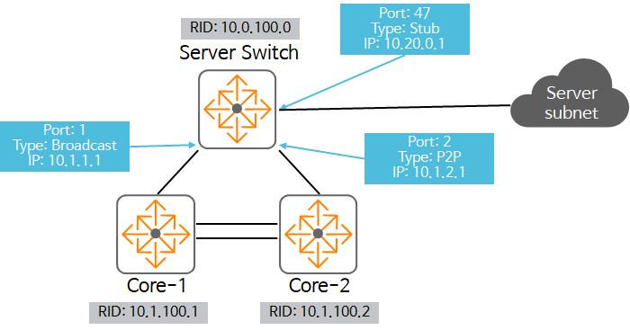
Port 1:
- Link Type: Broadcast
- RID: 10.0.100.0
- Link ID: 10.1.1.1 - DR's interface
- Data: 10.1.1.1 - IP address of the interface
Port2:
- Link Type: Point-to-Point
- RID: 10.0.100.0
- Link ID: 10.1.100.2 - Peer's RID
- Data: 10.1.2.1 - IP address of the interface
Port 47:
- Link Type: Stub
- RID: 10.0.100.0
- Link ID: 10.20.0.1
- Data: 255.255.240.0 - Subnet Mask
Okay, so let's analyze the information from the Core-1 and Core-2 perspectives.
First, the Stub Link Type includes the Subnet and Mask, which is enough information to run the SPF algorithm locally and reach the destination.
The P2P interface also includes the peer's router ID and information about the local interface being used. If the link details are incomplete from Core-1's perspective, Core-1 needs data from other peers on the link.
This information will be known to Core-1 when it receives an LSA Type 1 from Core-2. Once it receives information from both sides, Core-1 can also run the SPF algorithm.
Finally, the broadcast interface only contains the IP address of the router ID, but in this case, it uses LSA Type 1 and does not include subnet information. Consequently, the SPF algorithm cannot be executed.
How should I solve this case?
That's right, using LSA Type 2.
In AOS-CX “show ip ospf lsdb” You can check this information using the command:.
OSPF LSA Type 2
LSA Type 2 is used when there is a broadcast Network Type Link with a DR and BDR selected.
Point-to-Point network routers do not generate LSA Type 2. In this case, the Link-state ID is the IP address of the designated router (DR). These LSAs are called network LSAs because they advertise the network for which the router is the DR.
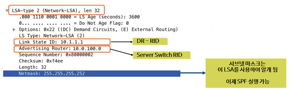
The image above is a screen capture of a packet with a Netmask included in an LSA using Wireshark.
With this information, the missing information in LSA Type 1 can now be resolved, allowing the SPF algorithm to be executed.
“show ip ospf lsdb” In the output from the command, the Network Link State Advertisement section shows the DR list.
Route selection
After all routers successfully exchange Link State Advertisements (LSAs) and Link State Updates (LSUs), they all have the same Link-State Database (LSDB). The LSDB contains a list of all routes and routers, and stores how these routers and links are connected. In other words, it contains a list of all routes.
The router must now run Dijkstra's algorithm, also known as the Shortest Path First (SPF) algorithm, to find the best path for each destination subnet. The best path is the one with the lowest cost, and the cost is based on bandwidth.
Therefore, if there are multiple routes to a single subnet, OSPF chooses the route with the lowest cumulative cost, i.e., the fastest route.
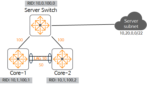
Consider the topology in the figure above. Core-1 has two routes to the destination subnet 10.20.0.0/22.
To determine the cost of each path, simply add the values displayed on each link.
- When using Core-2 as the next-hop: the cost is 50 + 100 = 150
- When using Server-Swtich as the next-hop: the cost is 100 = 100
That is, the route that uses the Server-Switch as the next-hop is the cheapest, so that route is added to the routing table.
OSPF convergence
There are two elements to OSPF routing convergence:.
- Topology change Detect (Detection)
- channel Recalculate (Recalculation)
Topology change detection is supported in two ways in OSPF:.
The first is the fastest way, a failure or change in the state of the physical interface.
The second is the OSPF Hello timer timeout. If a Hello packet doesn't arrive for a period of time longer than the dead timer for the Hello packet, the OSPF neighbor is considered to have a problem. By default, the dead timer is four times the timer value of the OSPF Hello packet. Since the default Hello timer is 10 seconds, if a Hello packet doesn't arrive for 40 seconds, the dead timer expires and the neighbor is considered to have a problem.
When a change is detected, an LSA is sent to all routers in the OSPF area to notify them of the topology change.
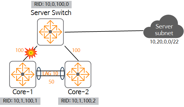
As shown in the figure, if a failure occurs in the link between Core-1 and Server Switch, both Server Switch and Core-1 detect this failure.
The link changes from UP to DOWN, and the Server Switch and Core-1 generate a topology change LSA.
Then, it runs the SPF algorithm to recalculate the best route to all affected networks, such as 10.20.0.0/22.
Here, the Server Switch uses the directly connected path without any changes, but for Core-1, the path is recalculated and the path goes through Core-2 instead of the original Server Switch.
Here Core-2 receives an LSA about the change, but in this case it does not need to recompute it.
Each router recalculates its routes after detecting a failure. In other words, all routers recalculate all routes using the Dijkstra (SPF) algorithm.
passive interface
Configuring OSPF requires enabling the protocol on both logical and physical interfaces.
Therefore, the router can advertise the subnet to other routers by generating LSAs. This means that the router periodically sends Hello messages on all OSPF-supporting interfaces.
However, in some cases, this may be unnecessary. For example, if there are only hosts on the subnet, the router will continue to send OSPF packets even if there are no other network devices. Host devices will not respond to OSPF multicast packets sent to 224.0.0.5 or 224.0.0.6. This simply wastes bandwidth within the link. Furthermore, if a malicious user is on the link, they can learn about the network and potentially prepare an attack.
A solution to this is to manually configure the host-facing router interface.
If an interface is passive, it stops sending and receiving OSPF packets on that interface. However, it continues to advertise that interface to other routes.
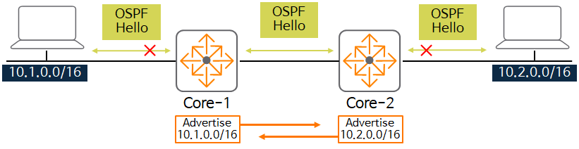
In the figure, Core-1 doesn't send Hello packets to the 10.1.0.0/16 network, but it does notify Core-2. Core-2 also only notifies Core-1 about the 10.2.0.0/16 network.
In AOS-CX, in the interface Context “ip ospf passive” You can enable a passive interface using the command:.
Switch(config)# interface
Switch(config-if)# ip ospf passive
OSPF Configuration Practical Example
So, based on what we've learned so far, let's see how to configure it on an actual AOS-CX switch.
1. Activate the OSPF process
Switch(config)# router ospf2. Configure Router ID
Switch(config-ospf-1)# router-id3. Create OSPF Area ID
Switch(config-ospf-1)# area4. Enable OSPF on the interface
Switch(config-if)# ip ospf area5. Network Type Settings
Switch(config-if)# ip ospf network {broadcast | point-to-point}6. OSPF cost settings (optional)
Switch(config-if)# ip ospf costThis is a brief overview of OSPFv2.
Even though I only touched on the very basics, this was a longer post than I expected.
OSPF is the most widely used routing protocol in the field, so it's essential to understand its related terminology, technologies, and troubleshooting methods. While a bit challenging and complex, it's a technology you can't afford to miss.
Now, the ACSA training course is almost over. Now, let's wrap up with management and operations-related content.