RSTP (Rapid STP) operates a loop-free topology through the following algorithm:.
- Select Root Switch
- Select the root port (RP) of any non-root switch or non-designated bridge switch.
- Select a designated port (DP) for the link connected between each switch
- Other ports operate in a blocked state to prevent loops.
Select Root Switch
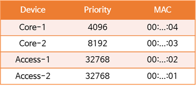
In both the STP (802.1d) and RSTP (802.1w) standards, the root switch is selected based on the Bridge ID (BID), with the lowest value taking precedence. The BID, which is divided into two parts, consists of a priority (default value 32,768) and a unique MAC address.
While you can use these default values, it's not recommended because it can lead to unexpected behavior. This is because the access switch located at the edge of the network topology can become the root switch. This results in a less optimized configuration, which in turn reduces resiliency and stability.
If the Priority is set to the default value of 32768 as shown in the table below, the Access-2 switch will become the root switch.
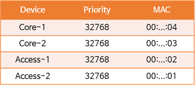
So, as shown in the picture, we want to make the Core-1 switch located in the center the root switch.
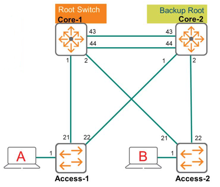
If the Core-1 switch becomes the root switch, the tree structure will be more robust, resilient, and have optimal paths. To achieve this, lower the priority of the Core-1 switch. If the priority of the Core-1 switch is lowered significantly, such as to 4096, the Core-1 switch will become the root switch because it has the lowest BID. However, if the Core-1 switch fails, the Access-2 switch will still become the backup root switch. To prevent this, the priority of the Core-2 switch must also be lowered (to a higher value than the Core-1 switch).
※ The priority value is Set in units of 4096I have to do it.
Selecting the Root Port of a Non-Root Switch
A non-root switch or non-designated bridge must select a root port (the port connected to the optimal path) to determine the optimal path to the root switch. The criteria for selecting a root port are as follows:.
- Lowest root bridge ID
- Lowest path cost to the root bridge
- Lowest sender bridge ID
- Lowest port priority
- Lowest port ID
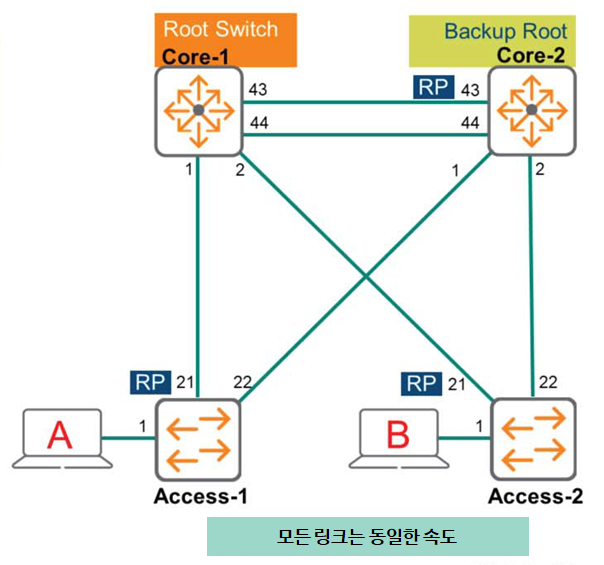
In the above diagram, the Core-2 switch receives BPDUs on ports 1, 2, 43, and 44. The Core-2 switch needs to determine which port is most appropriate. Let's take a look at the following:
Lowest root bridge ID
Based on the prioritization values, we agree that the Core-1 switch has the lowest BID and is therefore the root switch. This criterion doesn't help in selecting the best path.
Lowest path cost to the root bridge
If all links have the same speed, ports 1 and 2 on the Core-2 switch are indirect paths with a high cost. Therefore, these paths are discarded. Furthermore, ports 43 and 44 have the same cost, so the following criteria must be considered.
Lowest sender bridge ID
This also doesn't help since the BPDUs received on ports 43 and 44 are coming from the same Core-1 switch, so we need to look at the next criteria.
Lowest port priority
The sender (Core-1) includes a port priority in the advertisement. The port priority is a value between 0 and 240., The default value for the AOS-CX switch is 128The switch recognizes that the lower this priority value, the higher the priority. If you haven't changed any of the switch's default values, the values for both ports (ports 43 and 44) will be the same, so you'll need to decide based on the following criteria.
Lowest port ID
The final decision is made based on the port ID value. Since port 43 on the Core-1 switch is lower, port 43 on the Core-2 switch connected to it becomes the root port (RP).
The Access-1 switch also determines the root port according to the same criteria and order as above.
As with the Core-2 switch, the lowest root bridge ID doesn't help determine the optimal path. However, if all links are the same speed, port 21 has a lower path value to the root switch than port 22. This is because port 22 is an indirect path, resulting in a higher path cost.
Therefore, port 21 becomes the root port (RP).
The Access-2 switch also receives BPDUs on ports 21 and 22, and port 21, which has a lower cost, becomes the root port (RP).
In this way, we have learned the logic for selecting the root switch and root port in the RSTP topology.
Okay, so let's see how to select a designated port (DP).
Select Designated Port (DP)
The criteria for selecting a specified port are the same as for the root port.
- Lowest root bridge ID
- Lowest path cost to the root bridge
- Lowest sender bridge ID
- Lowest port priority
- Lowest port ID
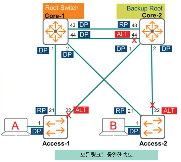
The following shows how to designate a designated port (DP) for each switch in the topology in the figure above.
Core-1 switch
Since the Core-1 switch is the Root Switch, all ports are close to the Root Bridge. In other words, all ports become DPs.
Core-2 switch
Let's look at the Core-2 switch, excluding port 43, which is the root port (RP).
Port 1
The Core-2 switch determines whether port 1 is closest to the root. This verification process is performed by comparing it with the BPDU signal received from Access-1. We will proceed according to the criteria mentioned above.
- Lowest root bridge ID: All devices in the topology agree that the Core-1 switch is the root. This means that this value is the same for all devices.
- Lowest path cost to the root bridge: Both the Access-1 and Core-2 switches have the same value (Cost) because they are 1 hop apart.
- Lowest sender bridge ID: Because the BID value of the Core-2 switch is lower, it is used on the link between the two switches. Port 1 of the Core-2 switch becomes DP.
Port 2
The Core-2 switch again checks whether this port is closest to the root. It does so by comparing the BPDU received from the Access-2 switch, just as it did with port 1.
- Lowest root bridge ID: All devices in the topology agree that the Core-1 switch is the root, i.e., it is the same as port 1.
- Lowest path cost to the root bridge: Since the link speed between each switch is the same, both switches that are one hop apart have the same value (Cost).
- Lowest sender bridge ID: Because the BID value of the Core-2 switch is lower, it is used on the link between the two switches. Port 2 of the Core-2 switch becomes DP.
Port 44
DP cannot be specified because the port on the other side of the two switch links (Core-1 switch) is closest to the root.
Access-1 switch
Port 1
This port is the only RSTP speaker on the connected link, meaning it is not connected to any other switches. Therefore, this port becomes DP.
Port 22
DP cannot be specified because the other port (Core-1 switch) of the link connected to this port is closest to the root.
Access-2 switch
Same as Access-1 switch, port 1 cannot be DP and port 22 cannot be DP.
The above diagram illustrates a topology without a Layer 1 hub. Therefore, there are no backup ports, only alternative ports. Any port not designated as a DP (designated port) or RP (root port) becomes an ALT port and is in the Discarding state. In the diagram, you can see that port 44 on the Core-2 switch and port 22 on the Access-1 and Access-2 switches have become ALT ports.
RSTP Edge Port & Link Type
Edge ports are connected to endpoints and therefore do not receive BPDUs. Endpoints do not need to participate in the Spanning Tree algorithm because they cannot create loops. This is called "leaf-on-the-spanning-tree." Because loops cannot be created, they can quickly transition to the Forwarding state without any intermediate steps.
If a BPDU is received on an edge port, the port operates as a normal spanning tree port and participates in the algorithm to prevent Layer 2 loops. Therefore, you must manually configure the edge port as follows.
Switch(config)# interface 1/1/1
Switch(config-if)# spanning-tree port-type admin-edge
As an alternative to the admin-edge option, the AOS-CX management network option is available. This option causes the port to listen for BPDUs for the first three seconds after the link is up. If no BPDUs are received, the port becomes an edge port and immediately forwards frames. If a BPDU is detected, the port becomes a non-edge port and participates in normal STP operation.
Switch(config)# interface 1/1/1 Switch(config-if)# spanning-tree port-type admin-networkRSTP topology change mechanism
In RSTP, a topology change occurs when a non-edge port changes to a different state or stops receiving BPDU values. The switch detects this topology change and notifies other switches in the network of the change. It sets the TC (Topology Change) bit in the BPDU and sends these BPDUs, flushing the MAC address table entries associated with all non-edge ports.
Other switches receive BPDUs with the TC (Topology Change) bit set from their neighbors. These switches clear the MAC address table entries on all ports except the port receiving the TC BPDU. These switches then, in turn, transmit BPDUs with the TC bit set.
reference: In the original 802.1d standard, any switch could advertise itself to other switches by sending TC BPDUs, but the command to clear the MAC address table always had to come from the root switch. This two-step process took longer to complete.
This post was a bit long. Spanning Tree is a crucial technology in increasingly complex network environments. A loop can cause significant problems across the entire network, so it's crucial to thoroughly understand this aspect.
In the next post, we will look at MSTP (Multiple Spanning Tree Protocol).