Layer 2 two-tier designIt is simple to deploy, operate, and troubleshoot because it uses existing traditional protocols.
You can handle it without any specialized knowledge of overlay protocols or complex designs.
This architecture Suitable for small and medium-sized data centersBut in a larger environment Data Center POD UnitIt can also be implemented as:.
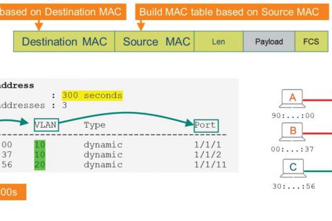
In a 2-tier data center, host information is traditionally Bridge Learning1(bridge learning) 및 ARP2 It is managed in this way.
Today we'll take a closer look at L2 two-tier design.
We will take a comprehensive look at how to plan VLANs and routing by understanding what L2 two-tier design is, how it is implemented, the characteristics of core design and access switch design, and the VLAN and routing requirements required for this architecture.
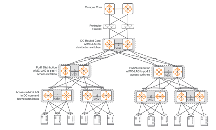
Layer 2 two-tier data center design
Layer 2 two-tier data center network Implement aggregation and L3 services at the data center core layer and provide endpoint connectivity at the L2 access layer.All access switches are connected to two core switches at L2 using Multi-Chassis Link Aggregation Group (MC-LAG) for load sharing and fault tolerance.
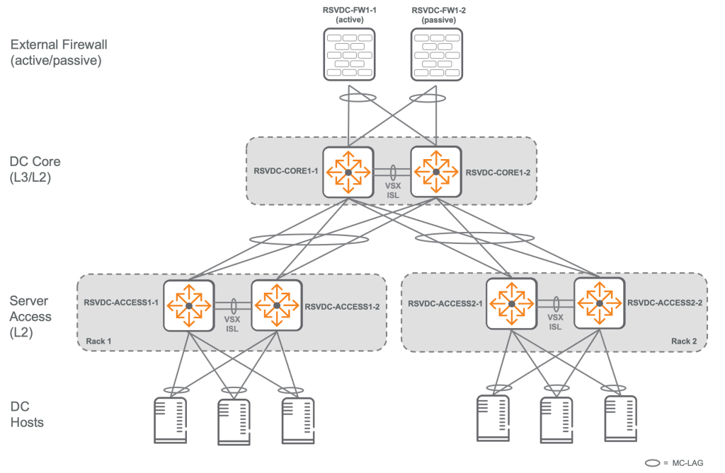
The physical layout of the L2 two-tier design is Matches a spine-leaf architecture with two spinesdo.
This protects future investments in L2 two-tier networking equipment. Migration path to EVPN-VXLAN overlay using L3 spine-leaf underlayin the file.
The core layer is all for the data center hosts. L3 function, and provides connectivity with external networks and services. connection pointThis is it.
Therefore, a redundant gateway protocol such as Virtual Router Redundancy Protocol (VRRP) is required.
Core layerhas high-density, high-bandwidth ports Deployed as a pair of VSX (Virtual Switching eXtension) switchesIt will work.
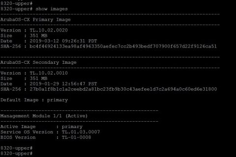
For this, two core switches are required. Same switch modelIt must continue Same firmware versionYou need to run it.
Core switch Port capacityis supported in a layer 2 two-tier architecture. Define the maximum number of racksdo.
For redundant ToR designs, the maximum rack count is half the total number of ports on the core switch model minus the number of VSX and campus links.
For example, if a 32-port switch uses two VSX links and two campus uplinks...
It can support 14 redundant ToR racks: (32-4)/2 = 14.
In non-redundant single-switch ToR designs, the number of supported racks is equal to the number of ports on the core switch model minus the number of VSX and campus links.
The core switch model is also part of the data center backbone. Define maximum capacitydo.
One advantage that a routed L3 spine-leaf architecture has over an L2 two-tier architecture is that it allows you to increase the capacity of the east-west backbone of your data center by adding spine switches. Gradually expandThe point is that you can do it.
For example, adding one spine to a two-spine fabric increases capacity by 50%, and adding two spines doubles the capacity. In contrast, an L2 two-tier design has only a single pair of VSX switches at the core to support inter-rack communication.
Therefore, in the L2 two-tier data center Capacity planning is very importantdo.
Because large capacity upgrades are usually Request hardware replacementBecause it does.
Sometimes, some racks may require higher capacity links to the core switch to provide high-bandwidth centralized services.
Between core switch and access switch Mismatch in uplink capacity affects host mobility.It should be noted that:.
Because VMs requiring increased bandwidth may only need to be connected to specific switches.
Core Design – Scaling: How to Scale the L2 Two-Tier Architecture
When you need to scale your L2 two-tier environment, one way to scale is Adding a third layer that connects separate L2 two-tier segments.no see.
This method can be used to group multiple data center PODs (modules) into a single data center network topology.
If appropriate, the third layer is MC-LAG3It can be connected to L2 using SVI4When moving to the third layer, VLANs can be used between PODs. If VLANs can be isolated to each POD, it is possible to use VLANs between individual L2 two-tier segments. Use routed links for load balancing and fault tolerance.You can do it.
To summarize:
When scale beyond the traditional two-tier architecture is needed, the L2 two-tier design introduces a new 'third tier' that allows multiple smaller L2 two-tier data center PODs to be interconnected.
This connection can be made in either L2 (MC-LAG) or L3 (routed) fashion, with L3 connections being useful for traffic distribution and increased reliability.
In particular, limiting VLANs within each POD and leveraging L3 connectivity enables efficient scaling while managing network complexity.
Access Layer Design: The Core of L2 Two-Tier Architecture
In an L2 two-tier architecture, each ToR access switch is connected to both core switches using MC-LAG.
This is Link load balancing (traffic distribution) and fault toleranceis to provide.
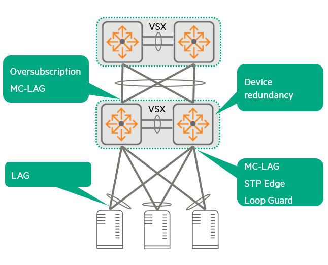
To add fault tolerance to downstream hosts (servers, etc.) VSX5Dual ToR pair usingThis is recommended.
L2 connectivity between access switches and core switches is MC-LAG and LACP.6 Through implementation loop-free Maintain the status.
However, to prevent data center administrators from accidentally creating loops within the rack, Backup Loop Prevention Strategiesby STP is configuredIt will work.
The core VSX pair is configured with high STP priority to be elected as the STP root.
MC-LAG is MST7 Between cores and access switches rather than implementing instances Better link utilizationIt provides.
This is because all redundant links remain active to carry traffic.
Traffic is applied based on detailed flow. Hash-based algorithmare delivered via individual LAG member links selected by .
On the other hand, MST instances can also provide fault tolerance and distribute traffic by using multiple links between access switches and core switches, but the load balancing strategy static configuration, demanding, Restrict active traffic forwarding to a single redundant link per VLAN.do.
That is, MC-LAG distributes traffic by utilizing all links simultaneously, but MST sends traffic of a specific VLAN through only one path, leaving other paths as backups.
From a performance perspective, the number of interfaces, media type, and speed (matching server interfaces) are very important aspects in access layer planning.
Uplink plan is as per customer requirement oversubscription rateshould be taken into consideration.
To summarize,
Access layer design is a critical component connecting servers and the core network in an L2 two-tier architecture. Link redundancy, load balancing, and switch redundancy are achieved by utilizing MC-LAG and VSX, while STP serves as a loop prevention device in emergencies. In terms of performance, server connection speeds and uplink bandwidth must be carefully planned to meet customer requirements.
VLAN and Routing Planning for Two-Tier Architecture
Planning VLANs and routing in a two-tier architecture is critical to building an effective data center network.
1. Non-virtualized “bare metal” servers:
- In a campus network, the edge port (the port where the end device connects) is almost always Access modeIt operates as a tagged transport and sends untagged traffic.
On the other hand, the uplink of the access layer (the link to the upper switch) Trunk modeIt operates as a VLAN and uses VLAN tags to transport multiple VLANs to the aggregation or core layer.
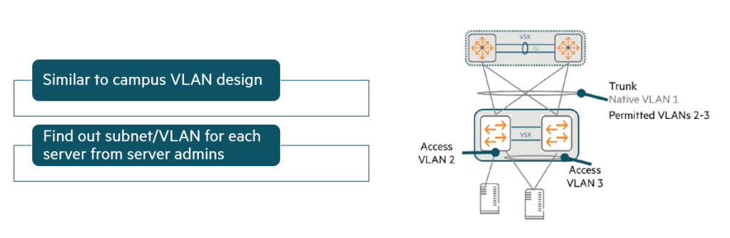
- A similar design is used when the switch is connected to non-virtualized (“bare metal”) servers.
To determine the correct access VLAN assignment for each switch port: Work with your server administratorMust do.
2. VMware host (virtualization server):
- However, the design is different when the access layer switch is connected to a virtualization server (VMware or Hyper-V host).
At this time, the edge port is usually trunk portIt should be.
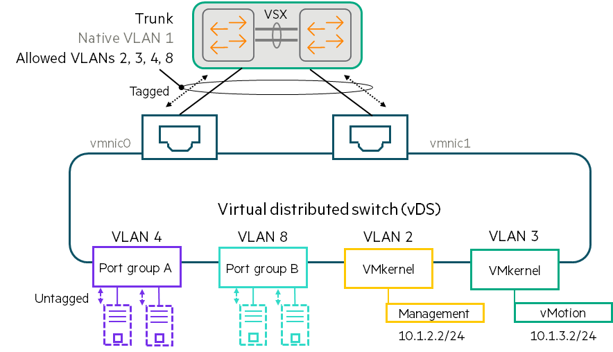
- The figure above shows a VMware host design using a Virtual Distributed Switch (vDS).
As previously explained, VMs are connected to vDSs within port groups. Each port group is associated with a specific VLAN. - For example, an administrator can assign VLAN 4 to Port Group A and VLAN 8 to Port Group B to ensure that these VMs are divided into different VLANs and subnets.
- vDS receives untagged traffic from VMs.
Traffic between VMs within the same port group is passed directly without going through physical links. - Alternatively, the vDS sends traffic over one of the physical links. Add a VLAN tag to the port groupdo.
In this way, the vDS instructs the physical switch to separate port group A traffic from port group B traffic. - VMkernel adapter It also has VLAN assignments.
- The network manager Coordinate VLAN design with virtualization managersMust do.
You need to get a list of VLANs used by each vDS and allow the edge ports connected to that vDS to use those VLANs.
※ Special cases:
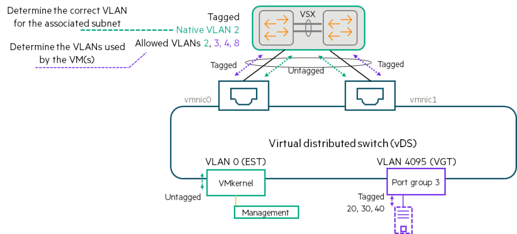
VLAN 0 (External Switch Tagging – EST):
- When a VMkernel or port group is assigned to VLAN 0 (sometimes called EST), the virtual switch will Untagged trafficSend it.
- You need to determine the correct VLAN for that traffic.
Then, connect that VLAN to the trunk port. Native VLANmust be allocated as . - A VMkernel or VM assigned to VLAN 0 on one virtual switch may be on a different subnet than a VMkernel or VM assigned to VLAN 0 on another virtual switch. Therefore, you must carefully select the correct VLAN for each subnet.
VLAN 4095 (Virtual Guest Tagging – VGT):
- This setting is not used very often, but you may come across it.
- When a port group uses VGT, the virtual switch will Allow traffic with all VLAN tagsdo.
- The virtual switch forwards traffic to the physical switch with VLAN tags intact.
- Which VLAN tag to use Coordination with the guest OS managerMust do.
Strict Permitted VLAN Design for Virtualized Environments
The figure below shows a design that precisely matches the allowed VLANs between the switch ports connected to VMware vDS.
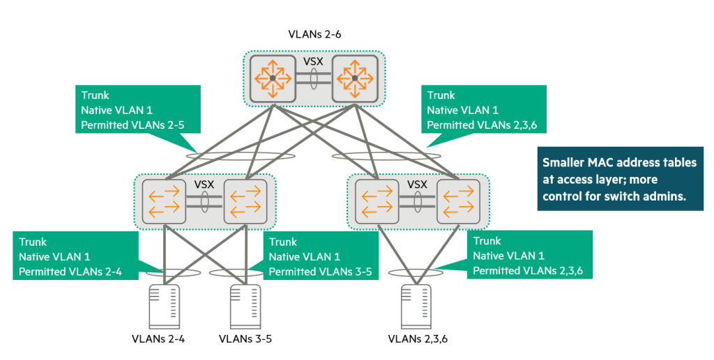
- For example, if a VMware ESXi host cluster has vDSs using VLANs 2-4, and these hosts are connected to the left VSX pair with LAGs 1-12, the switch will only allow VLANs 2-4 on LAG 1-12.
- If another VMware cluster uses a vDS that supports VLANs 2, 3, and 6, the LAG connected to that host will only support VLANs 2, 3, and 6, not VLANs 4 and 5.
This design approach allows VLANs to be expanded across cores as needed, but avoids the need to expand unnecessary VLANs.
This design is for the switch administrator. More controlIt provides.
Administrators can see exactly how far a VLAN extends, and must request approval if a user wants to extend a new VLAN.
Each access layer switch only needs to learn the MAC addresses for the VLANs on which it actively handles traffic.
If a customer has access layer switches with small MAC table sizes, this strict control can help data center scaling by preventing the MAC table from being overflowed with unnecessary addresses.
Loose Permitted VLAN Design for Virtualized Environments
Sometimes customers want their virtualization administrators to be able to make changes more easily without having to coordinate with physical network administrators.
In this case, the edge port and uplink Trunk allowing all VLANscan be composed of.
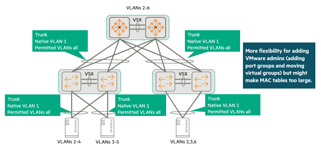
Virtualization administrators can then freely add or change port groups and virtual switch settings on the host without worrying about whether the connected switch ports support the correct VLANs.
However, the switch Allow VLANs only if the VLAN actually exists on the switch.It should be noted that:.
The virtualization administrator must provide the switch with the block of VLAN IDs that it wants to support in each rack so that it can create those VLANs.
This slightly looser approach gives customers more flexibility.
On the other hand, a switch may end up supporting more VLANs than strictly necessary.
The switch learns MAC addresses from all VLANs configured on it.
This should be kept in mind when validating the MAC address table size of a proposed switch.
In a relatively small data center, any CX data center switch can easily meet your needs.
However, in larger networks, a more prudent approach is to further segment VLANs or use overlay networking.
No matter which approach you choose with your customers for VLAN extensions, virtualization and network administrators will still need to coordinate some settings.
If a virtualization administrator wants to add a new VLAN/subnet, the network administrator must add an L2 VLAN to all switches in the data center.
You will also need to add a L3 VLAN interface on the core, configure DHCP relay, and advertise the new subnet in the routing protocol.
Considerations for Ensuring Loop-Free Design
1. First line of defense:
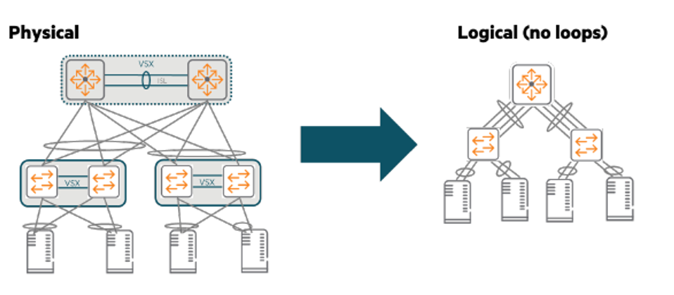
This two-tier network extends VLANs across the access layer and routes traffic in the core.
So we have to be very careful to avoid L2 loops.
Possible through VSX VSX LAG-based designprovides the first layer of protection.
As you can see in the picture above, VSX LAG means that there are no loops in the network at the logical level.
2. Second line of defense:
You should also add a second layer of defense against misconfigurations.
For example, an administrator might accidentally create two separate VSX LAGs between a VSX pair in some racks and two core switches.
Because we don't want to bring down the network due to a loop caused by mistake.
For this second line of defense, we use the open standard MSTP.
Manually configure the core switch to have the highest root priority (0).
The core switch with the lowest MAC address becomes the root.
It doesn't matter which core switch becomes the root, as long as it's a core switch and not an access layer switch.
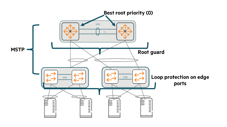
Enable Root Guard on core switch interfaces to prevent a rogue or misconfigured switch from becoming root.
MSTP should notify customers that a delay of several seconds may occur when a new port becomes active.
To avoid this delay, implementers should configure all edge ports Spanning Tree Edge PortIt must be composed of:.
Or, the exclusive CX switch Loop detection functioncan also be applied to edge ports.
However, do not use this feature on ports between switches.
During normal operation, these auxiliary protocols should not block any ports.
However, if a loop is created due to an error, they will block the loop and protect the network.
Routing Design for Two-Tier Networks: Data Center Internal and External Connectivity Strategies
In a two-tier network, routing design plays a key role in handling traffic within the data center and connecting it to external networks.
Data Center Internal Routing Design
Small two-tier data centers have simple routing designs.
Role of the Core VSX pair:
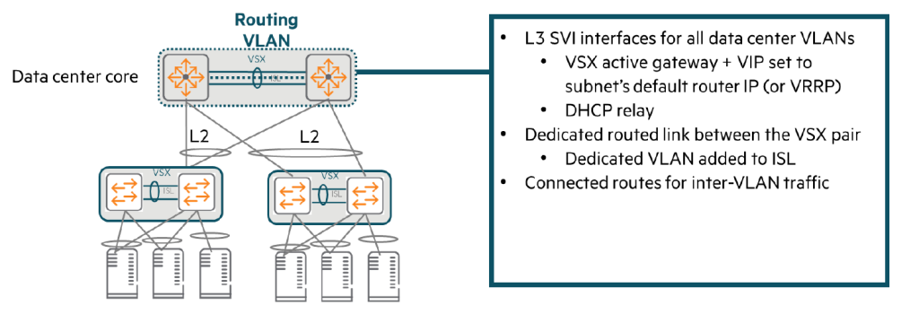
The core VSX pair is responsible for all server VLANs. Default Router It performs the role and handles functions such as DHCP relay.
At this time, to provide redundancy of the default router IP address, VSX Active Gateway FunctionIt is important to use .
With an active gateway, there is no need to separately configure Virtual Router Redundancy Protocol (VRRP).
Routing traffic within the data center:
A pair of core VSXs can route all traffic within a data center using directly connected routes.
Add a dedicated routing link to the VSX ISL:
VSX ISL (Inter-Switch Link) Add a separate VLANSo you need to set up a dedicated routing link.
This VLAN should only be used on ISLs within the same subnet on each switch. /31 Assign an IP address.
Routing protocols are configured over this link to allow switches to route traffic to each other in the event of a failure.
Routing design between data centers and other parts of the network
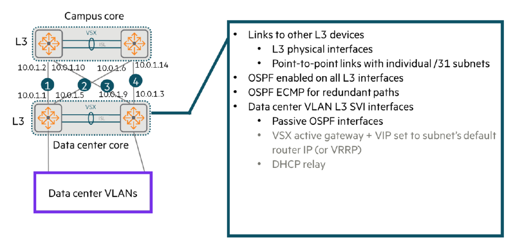
Data center core switches use Layer 3 (L3) connectivity to reach other devices, including:.
- Internet routers or perimeter firewalls
- Wide Area Network (WAN) routers
- Campus routing switches
Typically these connections include: We do not recommend using VSX LAG.
Instead, each link L3 interface Or set it to a Route-Only Port (ROP).
Individual /31 Establish a point-to-point link using subnets.
Then, we work with our customer network architect to: Determine the correct routing protocolMust do.
In the example below, the common choice is OSPFAlthough focused on RIP, CX switches also support RIP and BGP.
When using OSPF:
Enable OSPF on all SVIs and L3 physical interfaces. The switches will then establish adjacency relationships with other routing devices, such as campus core switches.8, and advertise a route to the server subnet to its neighboring devices.
Using ECMP:
Ensure that the cost is the same across all point-to-point links.
Then the switches will ECMP9Use it to route traffic between campuses and data centers across all those links.
Security measures:
- The SVI for the server subnet is set as a passive interface.
The core switch should not transmit routing information on that subnet. - In contrast, leave OSPF enabled on the routed transit VLANs of the VSX ISL.
The two VSX members must form an adjacency relationship on this VLAN and exchange routes.
So, to summarize...
- Inside the data center: The core VSX pair acts as the default router for all server VLANs, handling redundancy and internal routing via dedicated routing links from the active gateway and VSX ISLs.
- Outside the data center: Communicates with external networks using L3 connections and OSPF (or RIP, BGP).
At this time, load balancing is implemented using individual L3/ROP links and ECMP instead of VSX LAG, and the server SVI is set as a passive interface for security.
Today, we learned about 2-tier data center network design.
A two-tier design consists of two core switches (a pair of VSXs) and multiple access switches (ToRs) connected to them.
This simple design allows for easy deployment and operation in small and medium-sized data centers, but it comes at the cost of poor scalability.
Don't forget about the roles of core and access switches, as well as redundancy and load balancing through VSX, MC-LAG, etc.
- Bridge Learning: The process of automatically identifying the locations (MAC addresses) of devices connected to a network. ↩︎
- Address Resolution Protocol ↩︎
- Multi-Chassis Link Aggregation Group ↩︎
- Switched Virtual Interface ↩︎
- Virtual Switching eXtension ↩︎
- Link Aggregation Control Protocol ↩︎
- Multiple Spanning-Tree ↩︎
- Neighbor relationships ↩︎
- Equal Cost Multipath ↩︎