Previous PostFollowing this, this time we will cover more in-depth content.
Let's look at the commands needed to configure the functions required to actually operate a network in the field.
VLAN configuration
Here's how to create and configure VLANs and VLAN interfaces in AOS-CX:.
Although you can configure a single VLAN, the Range command allows you to easily create and assign multiple VLANs.
Create a single VLAN
switch(config)# vlan 10
switch(config-vlan-10)#
You can see that the VLAN has been created but not assigned to an interface.
switch(config)# show vlan 10
------------------------------------------------------------------ VLAN Name Status Reason Type Interfaces ------------------------------------------------------------------ 10 VLAN10 up ok static switch(config)#
Create multiple VLANs
switch(config)# vlan 70-75
switch(config-vlan-<70-75>)#
You can see that VLAN 70 to VLAN 75 have been created, but no interfaces have been assigned.
switch(config)# show vlan
--------------------------------------------------------- VLAN Name Status Reason Type Interfaces --------------------------------------------------------- 70 VLAN70 up ok static 71 VLAN71 up ok static 72 VLAN72 up ok static 73 VLAN73 up ok static 74 VLAN74 up ok static 75 VLAN75 up ok static switch(config)#
Assigning a VLAN to a specific interface
switch(config)# int 1/1/1
switch(config-if)# vlan access 10
switch# show vlan 10
------------------------------------------------------------------------------------- VLAN Name Status Reason Type Interfaces ------------------------------------------------------------------------------------- 10 vlan up ok default 1/1/1Interface configuration
AOS-CX supports various configuration options for Layer 2 interfaces.
You can check all options using the ? command.
switch(config-if)# int 1/1/1 ?
  aaa Configure Authentication, Authorization and Accounting feature app-recognition Configure application recognition parameters apply Apply a configuration record arp Configure ARP commands energy-efficient-ethernet Enable Energy-Efficient Ethernet port-access Configure Port Based Network Access. portfilter Block traffic received on this interface from forwarding to some ports power-over-ethernet Configure Power over Ethernet (PoE) … routing Configure interface as L3 sflow Enable sFlow show Show running system information shutdown Disable the interface spanning-tree Show Spanning-tree configuration speed Configure interface speed, duplex, and … vlan VLAN configuration vrf VRF Configuration vrrp VRRP information
L3 interface configuration
You can configure Routed Only Ports (ROPs) on interfaces to support L3 routing services.
The example below is 1/1/1 interfaceSet as L3 interface, 10.10.20.209/24 IP address와 OSPFHere's how to configure it.
switch# config switch(config)# interface 1/1/1
switch(config-if)# routing
switch(config-if)# IP address 10.10.20.209/24
switch(config-if)# ip mtu 9198
switch(config-if)# ip ospf 1 area 0.0.0.0
switch(config-if)# ip ospf network point-to-point
Configuring the Source Interface
The source IP address is usually determined by the system as the IP address of the sending interface in the routing table.
However, a routing switch may have multiple routing interfaces, and outgoing packets may be sent along different paths at different times.
At this time, the Source IP address will change.
AOS-CX supports the ability to define specific source interfaces based on service type.
switch(config)# ip source-interface ?
  all All protocols central Aruba Central protocol dhcp_relay DHCP_RELAY protocol dns DNS protocol http HTTP protocol ntp NTP protocol ptp PTP protocol radius RADIUS protocol sflow sFlow protocol sftp-scp SFTP and SCP protocols ssh-client SSH Client protocol syslog syslog protocol tacacs TACACS protocol tftp TFTP protocol ubt UBT
Below is an example of configuring a specific interface or a source interface for a specific VRF (green) to use the TFTP protocol.
switch(config)# ip source-interface tftp interface 1/1/1switch(config)# ip source-interface tftp interface 1/1/2 vrf greenConfiguring basic network services
Configuring NTP (Network Time Protocol)
AOS-CX supports NTP across all CX product lines.
NTP servers can be defined by IP address or DNS name. NTP also supports authentication, burst/burst, and VRF-specific configuration.
switch(config)# ntp server pool.ntp.org 4 minpoll 4 iburst

Enable NTP server
switch(config)# ntp enable
If you want to configure all NTP traffic to flow through the mgmt VRF, do the following:.
switch(config)# ntp vrf mgmtTo check NTP configuration information and status, use the show command as follows:.
switch(config)# show ntp associations
-------------------------------------------------------- ID NAME REMOTE REF-ID ST LAST POLL REACH ------------------------------------------------------------------------ * 1 lithium.consta 108.61.56.35 192.5.41.40 2 17 16 3 ------------------------------------------------------------------------
switch(config)# show ntp servers
------------------------------------------------ NTP SERVER KEYID MINPOLL MAXPOLL OPTION VER ------------------------------------------------ pool.ntp.org -- 4 4 iburst 4switch(config)# show ntp status
NTP Status Information NTP : Enabled NTP DHCP : Enabled NTP Authentication : Disabled NTP Server Connections : Using the default VRF System time : Wed Aug 7 23:20:10 UTC 2024 NTP uptime : 6 minutes, 2 seconds NTP Synchronization Information NTP Server : lithium.constan at stratum 2 Poll interval : 16 seconds
DNS configuration
AOS-CX supports per-VRF DNS configuration, and the number of settings per VRF is as follows:.
- Up to 3 nameservers
- Up to 6 domain names per VRF
- Up to 6 host names
switch(config)# ip dns domain-name switch.com
switch(config)# ip dns server-address 1.1.1.1
AOS-CX also supports associating a static IP address with a hostname.
The DNS client returns this IP address instead of querying a DNS server. You can define up to six hosts per VRF.
switch(config)# ip dns host myhost1 3.3.3.3The configured information can be checked using the show command.
switch# show ip dns
VRF Name : vrf_mgmt Host Name Address -------------------------------------------------------------------------- VRF Name : vrf_default Domain Name : switch.com DNS Domain list : Name Server(s) : 1.1.1.1 Host Name Address -------------------------------------------------------------------------- Myhost1 3.3.3.3
RADIUS configuration
AOS-CX has four basic groups that support authentication services:.
- tacacs: For remote AAA, always includes all configured TACACS+ servers.
- radius: For remote AAA, always includes all configured RADIUS servers.
- local: For local authentication.
- none: For local (RBAC) authentication.
switch(config)# radius-server ?
  auth-type Set authentication type. (Default: pap) host Specify a RADIUS server key Set shared secret retries Set the number of retries service-type Service-Type attribute status-server Configure status server parameters timeout Set the transmission timeout interval tls Configure TLS for the RADIUS server tracking Configure RADIUS service tracking parameters switch(config)# radius-server host 1.1.1.1 vrf mgmt
If you have multiple RADIUS servers, you can create a server group and add hosts to it.
switch(config)# aaa group server radius sg3
switch(config-sg)# server 1.1.1.4 vrf mgmt
Banner configuration
There are two levels of banners that users see when connecting via the CLI:.
- When you connect to the switch and are prompted to enter a password
- After the user is authenticated
Example usage: “IT department provides guidance on appropriate usage rules”
switch(config)# banner
  exec Set the exec (post-login) banner motd Set the message of the day banner
To set a banner to be displayed to all users who log in before the password entry screen appears. motd Use the command.
At the beginning and end of the banner text ^ (shift+6) You can use special characters to create the entire banner text.
switch(config)# banner ^
>> This is an example of a banner text which a connecting user >> will see before they are prompted for their password >> >> As you can see it may span multiple lines and the input >> will be terminated when the delimiter character is >> encountered. ^
Banner updated successfully!
If you want to set the phrase that is displayed when the user enters a password and is authenticated, exec Use the command.
This time, instead of the ^ special character, & (shift+7) Use special characters.
switch(config)# banner exec &
>> this is an example of a different banner text. This >> time the banner entered will be displayed after a >> user has authenticated. >> >> &This text will not be included because it comes >> after the &
Banner updated successfully
DHCP client configuration
The AOS-CX access switch operates as a DHCP client by default on VLAN 1 and the management interface (mgmt), automatically obtaining an IP address from a DHCP server on the connected network. The DHCP client can only be configured on one VLAN interface at a time.
If the interface has a static IP address and the DHCP client is enabled, the static IP address takes precedence.
If a static IP address is configured on the SVI, the dhcp configuration is ignored.
switch1(config-if-vlan)# int vlan 1
switch1(config-if-vlan)# show run cur
interface vlan 1 ip address 10.10.1.100/24 ip dhcp ! ip dhcp is ignored when static ip is configured
If you want other VLAN interfaces other than VLAN 1 to act as DHCP clients, you must disable the dhcp setting for VLAN 1.
switch(config-if-vlan)# int vlan 1
switch(config-if-vlan)# no ip dhcp
switch(config-if-vlan)# int vlan 70
switch(config-if-vlan)# ip dhcp
switch(config-if-vlan)# sho run current
interface vlan 70 ip dhcp
DHCP Relay Agent Settings
DHCP Relay Agent forwards DHCP messages from DHCP clients on a subnet that does not have a DHCP server to other subnets.
It also relays the DHCP server's response to the DHCP client.
DHCP Relay Agent is supported on Layer 3 interfaces, Layer 3 VLAN interfaces, and LAG interfaces.
DHCP relay is not supported in the management interface. DHCP relay option 82 is supported.
Here's how to configure DHCP relay on L3 SVI:.
switch(config)# int vlan 2
switch(config-if-vlan)# ip helper-address 10.10.1.102
switch(config-if-vlan)# sho run cur
interface vlan 2 ip address 10.10.2.100/24 ip helper-address 10.10.1.102
LAG (Link Aggregation Group) is configured as follows:.
switch(config)# int lag 20
switch(config-lag-if)# ip helper-address 10.10.1.102
switch(config-lag-if)# sho run cur
interface lag 20 no shutdown routing ip helper-address 10.10.1.102 lacp mode active
Configuring the DHCP server
The switch's DHCP server supports both IPv4 and IPv6 and can be configured independently for each VRF.
Multiple address pools and static address bindings are also supported.
※ On interfaces belonging to the same VRF You cannot enable both DHCP server and DHCP relay.
The example below shows how to create a dhcp pool named vlan2 in the default VRF.
- DHCP IP address range: 10.10.2.50 ~ 10.10.2.90 (24-bit)
- Default gateway: 10.10.2.250
- DNS servers: 208.67.220.220, 208.67.222.222
- Lease term: Permanent
switch(config)# dhcp-server vrf default
switch(config-dhcp-server)# pool vlan2
switch(config-dhcp-server)# range 10.10.2.50 10.10.2.90 prefix-len 24
switch(config-dhcp-server)# default-router 10.10.2.250
switch(config-dhcp-server)# dns-server 208.67.220.220 208.67.222.222
switch(config-dhcp-server)# lease infinite
switch(config-dhcp-server)# exit
switch(config-dhcp)# enable
You can also configure a DHCP server for a specific VRF called red.
switch(config)# dhcp-server vrf red
switch(config-dhcp-server)# pool 60
switch(config-dhcp-server)# range 10.10.60.10 10.10.60.15 prefix-len 24
switch(config-dhcp-server)# default-router 10.10.60.250
switch(config-dhcp-server)# lease infinite
switch(config-dhcp-server)# exit
switch(config-dhcp)# enable
DHCP server information configured in the default VRF can be checked using the show command.
switch# sho dhcp-server vrf default

VRF Name : default DHCP Server : enabled Operational State : operational Authoritative Mode : true Pool Name : vlan2 Lease Duration : infinite DHCP dynamic IP allocation ---------------------------- Start-IP-Address End-IP-Address Prefix-Length ----------------- --------------- ------------- 10.10.2.50 10.10.2.90 24 DHCP Server options *************************************************** Option-Number Option-Type Option-Value -------------- ------------ ------------- 3 ip 10.10.2.250 6 ip 208.67.220.220 208.67.222.222
STP (Spanning Tree Protocol) configuration
AOS-CX is basically MSTPIt supports RPVST+ as well.
To improve the performance and stability of MSTP, AOS-CX supports:
- admin-edge
- root-guard
- tcn-guard
- bpdu-guard
AOS-CX supports deterministic root bridge placement by applying a desired priority to each configured MSTI (instance).
switch(config)# spanning-tree ?
 bpdu-guard Disable he specific port if the port receives STP BPDUs config-name Set the MST region configuration name config-revision Set the MST region configuration revision number extend-system-id Enables the extended system-id functionality. forward-delay Set the forward delay for the Multiple spanning tree hello-time Set the hello interval for the Multiple spanning tree
Let's try out MSTP configuration by looking at the following example figure.
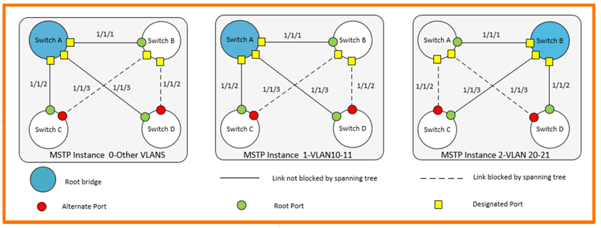
Switch A requires the following configuration:.
- Create VLAN 10-11, VLAN 20-21
- VLAN 10-11 is the root for instance 1
- VLAN 20-21 is the root for instance 2
- Root for CIST (Common Internal Spanning Tree)
- All VLAN traffic is enabled on interfaces 1/1/1-1/1/3.
SwitchA(config)# vlan 10-11,20-21
SwitchA(config-vlan-<10-11,20-21>)# exit
SwitchA(config)# spanning-tree
SwitchA(config)# spanning-tree config-name sp1
SwitchA(config)# spanning-tree config-revision 1
SwitchA(config)# spanning-tree instance 1 vlan 10-11
SwitchA(config)# spanning-tree instance 2 vlan 20-21
SwitchA(config)# spanning-tree priority 0
SwitchA(config)# spanning-tree instance 1 priority 0
SwitchA(config)# spanning-tree instance 2 priority 1
SwitchA(config)# int 1/1/1-1/1/3
SwitchA(config-if-<1/1/1-1/1/3>)# vlan trunk allowed all
SwitchA(config-if-<1/1/1-1/1/3>)# vlan trunk native 1
SwitchA(config-if-<1/1/1-1/1/3>)# exit
Check if MSTP configuration is correct using the show command.
SwitchA(config)# show spanning-tree mst-config
MST configuration information MST config ID: sp1 MST config revision: 1 MST config digest: 098798F08… 39604C10 Number of instances : 2 Instance ID Member VLANs --------------- ---------------------------------- 0 1-9,12-19,22-4094 1 10,11 2 20,21
SwitchA(config)# show spanning-tree summary root
STP status : Enabled Protocol : MSTP System ID : 08:00:09:8a:14:fa Root bridge for STP Instance : 0,1 Root Hello Max Fwd Inst ID Pri Root ID cost Time Age Dly Root Port -------- ---- -------- --- --- ------- ----- --- 0 0 08:00:09:8a:14:fa 0 2 20 15 0 1 0 08:00:09:8a:14:fa 0 2 20 15 0 2 0 08:00:09:12:8e:9e 20000 2 20 15 1/1/1AOS-CX allows connected station/device ports to forward data without going through the learning and receiving phase. admin-edgeSupports .
SwitchC(config-if)# spanning-tree port-type admin-edgeCheck the results with the show command.
SwitchC(config-if)# sho spanning-tree mst 1

#### MST1 Vlans mapped: 10,11 Bridge Address:08:00:09:16:7b:7e Priority:32768 Root Address:08:00:09:8a:14:fa Priority:0 Port:1/1/2, Cost:20000, Rem Hops:19 Port Role State Cost Pri Type -------------- -------------- ---------- ---------- ---------- 1/1/2 Root Forwarding 20000 128 P2P 5 2228 4 7 1/1/3 Alternate Blocking 20000 128 P2P 12 1/1/9 Designated Forwarding 20000 128 P2P Edge 2228 0 0 0
AOS-CX supports BPDU Guard and Root Guard to protect the spanning tree from spoofed BPDUs and rogue devices.
The example below shows how to configure BPDU guard on interface 1/1/8 of Switch D, which is connected to a switch that transmits BPDUs.
SwitchD(config)# int 1/1/8
SwitchD(config-if)# no shut
SwitchD(config-if)# vlan access 10
SwitchD(config-if)# spanning-tree bpdu-guard
Interface 1/1/8 is disabled due to received BPDUs.
SwitchD(config)# show spanning-tree mst 1

Port Role State Cost ---------- -------------- ---------- ---------- 1/1/8 Disabled Bpdu-Error 20000
OSPF configuration
AOS-CX supports OSPFv2 (default) and OSPFv3.
Open Shortest Path First version 2 (OSPFv2) is a routing protocol described in RFC2328.
A link-state-based interior gateway protocol (IGP) routing protocol applied to routers grouped into OSPF areas identified by the routing configuration of each routing switch. It is widely used in medium- to large-sized enterprise networks.
Each CX switch has a different OSPF table size depending on the model.
6300-switch(config)# show capacities ospfv2
System Capacities: Filter OSPFv2 Capacities Name Value ---------------------------------------------------------------------------- Maximum number of OSPFv2 areas configurable in the system 128 Maximum number of OSPFv2 interfaces configurable in the system 128 Maximum number of OSPFv2 interfaces per area in the system 128 Maximum number of OSPFv2 neighbors allowed across all VRFs 128 Maximum number of OSPFv2 processes supported across each VRF 8 Maximum number of routes in OSPFv2 supported across all VRFs 64000
When you configure the OSPF process ID, you will see several additional options.
6300-switch(config)# router ospf 1
6300-switch(config-ospf-1)# ?
  active-backbone Configure active backbone area Configure OSPF area parameters bfd BFD configuration commands default-information Generate a default external route into an ospf routing domain default-metric Configure metric of redistributed routes. disable Disable OSPF process distance Configure OSPF administrative distance distribute-list Filter networks in routing updates enable Enable OSPF process end End current mode and change to enable mode exit Exit current mode and change to previous mode graceful-restart Configure graceful-restart for OSPF list Print command list max-metric Configure to advertise maximum metric maximum-paths Configure maximum number of ECMP routes that OSPF can support --Abbreviate view
To configure OSPFv2 and loopback interfaces on SVI, proceed as follows:.
- OSPF configuration: router ospf [vrf ]
- Assigning a router ID
- OSPF area assignment
- Assign OSPF processes to loopback addresses (for reachability)
- Local and connected route redistribution
Define an OSPF instance in the global context.
switch# config
switch(config)# router ospf 1
switch(config-ospf-1)# router-id 1.1.1.1
switch(config-ospf-1)# area 0.0.0.0
switch(config-ospf-1)# redistribute connected
switch(config-ospf-1)# redistribute local
Create a loopback interface and assign it to OSPF 1.
switch(config)# interface loopback 0
switch(config-loopback-if)# IP address 1.1.1.1/32
switch(config-loopback-if)# ip ospf 1 area 0.0.0.0
Add OSPF to SVI.
switch# config
switch(config)# interface vlan 2
switch(config)# IP address 10.10.2.1/24
switch(config-if)# ip ospf 1 area 0.0.0.0
Let's check what we've configured so far.
switch(config-if)# show run current-context
Interface vlan 2 no shutdown no routing ip address 10.10.2.1/24 ip ospf 1 area 0.0.0.0 exit
Configuring OSPFv2 on ROP in P2P mode
The default mode is broadcast mode, but here's how to configure OSPFv2 on ROP in Point-to-Point mode:.
First, change the L2 port to L3 ROP.
switch# config switch(config)# interface 1/1/22
switch(config-if)# show run current-context
interface 1/1/22 no shutdown
    no routing
    vlan access 1 switch(config-if)# routing
switch(config-if)# show run current-context
interface 1/1/22 no shutdown
    routing
Configure OSPF on the changed ROP.
switch# config
switch(config)# interface 1/1/22
switch(config-if)# IP address 10.15.0.1/24
switch(config-if)# ip ospf 1 area 0.0.0.0
switch(config-if)# ip ospf network point-to-point
Check the configured information.
switch(config-if)# show run current-context
interface 1/1/22 no shutdown routing ip address 10.15.0.1/24 ip ospf 1 area 0.0.0.0 exit
OSPF show command
Check active OSPF neighbors
switch(config)# sho ip ospf neighbors
VRF : default Process : 2 =================================================== Total Number of Neighbors : 1 Neighbor ID Priority State Nbr Address Interface ---------------------------------------------------------- 2.2.2.2 n/a FULL 192.168.1.1 lag20
Check OSPF status
switch(config)# sho ip ospf
VRF : default Process : 1 ---------------------------------------------------- RouterID: 1.1.1.1 OSPFv2: Enabled BFD: Disabled SPF Start Interval: 200 ms SPF Hold Interval: 1000 ms SPF Max Wait Interval: 5000 ms LSA Start Time: 5000 ms LSA Hold Time: 0 ms … . Area : 0.0.0.0 ---------------- Area Type: Normal Status : Active Total Interfaces: 1 Active Interfaces: 1
View OSPF interface summary
switch(config)# sho ip ospf interface brief
OSPF Process ID 1 VRF default ============================= Total Number of Interfaces: 3 Flags: P - Passive A - Active Interface Area IP Addr/Mask Cost State Status Flags --------------------------------------------------------------- lag20 1.1.1.1 192.168.1.2/30 50 Pt-Pt Up A loopback5 1.1.1.1 3.3.3.3/32 0 Loopback Up A vlan70 1.1.1.1 10.10.70.1/24 100 DR Up A
Verify OSPF routing in the IP routing table
switch(config)# sho ip route ospf

Displaying ipv4 routes selected for forwarding VRF: default Prefix Nexthop Interface VRF(egress) Origin/ Distance/ Age T Type Metric ---------------------------------------------------- 0.0.0.0/0 10.10.1.250 vlan1 - O/E2 [110/10] 02d:23h:51m 1.1.1.1/32 10.10.1.250 vlan1 - O/E2 [110/10] 02d:23h:51m 10.10.56.0/24 10.10.1.250 vlan1 - O/E2 [110/10] 02d:23h:51m 10.10.98.0/24 10.10.1.250 vlan1 - O/E2 [110/10] 02d:23h:51m 10.10.222.0/24 10.10.1.250 vlan1 - Total Route Count : 5
LAG (Link Aggregation Group)
AOS-CX supports both L2/L3 LAG, and LAG is Static by default.
The CX operating system supports both LACP Active/Passive mode and LACP fallback-static mode, which allow data to be forwarded to a single member port even if the LAG is in an error or down state due to a mismatch.
Create a static L2 LAG
Let's create a Static L2 LAG with two members as Native VLAN 1.
When creating a LAG, you can create it with the LAG number along with the Interface command. (# int lag <1-256>)
switch(config)# int lag 20
switch(config-lag-if)#
We will allow forwarding of VLAN 60 and VLAN 70 on the LAG we created.
switch(config-lag-if)# no routing
switch(config-lag-if)# vlan trunk allowed 60,70
switch(config-lag-if)#
Check if the applied settings are correct show running-config current-context You can check it with the command.
switch(config-lag-if)# show run current
interface lag 20 no routing vlan trunk native 1 vlan trunk allowed 1,60,70
Add a physical interface to the created LAG. The range command is convenient for adding interfaces.
switch(config)# int 1/1/2,1/1/3
switch(config-if-<1/1/2,1/1/3>)# lag 20
If you check the settings for each interface, you can see that the LAG settings are included.
switch(config-if-<1/1/2,1/1/3>)# sho run cur
interface 1/1/2 lag 20 exit interface 1/1/3 lag 20 exit switch(config-if-<1/1/2,1/1/3>)# exit
Switch(config)#
If nothing is connected to a member port (interface) of the created LAG, the status of the LAG is shown as Down.
switch(config)# show interface lag 20
 Aggregate lag20 is down
 Admin state is down
 State information: Admin state is down
 Description : MAC Address : 08:00:09:3f:27:18 Aggregated-interfaces : 1/1/2 1/1/3 Aggregation-key : 20 Speed : 0 Mb/s L3 Counters: Rx Disabled, Tx Disabled qos trust none VLAN Mode: native-untagged Native VLAN: 1 Allowed VLAN List: 1,60,70 Statistic RX TX Total ---------------- ------------- ------------- -------- Packets 0 0 0 Unicast 0 0 0 Multicast 0 0 0 Broadcast 0 0 0 Bytes 0 0 0 Jumbos 0 0 0 Dropped 0 0 0 Pause Frames 0 0 0 Errors 0 0 0 CRC/FCS 0 n/a 0 Collision n/a 0 0 Runts 0 n/a 0 Giants 0 n/a 0
If another switch is connected to LAG 20, the status will be displayed as up as shown below.
switch(config-lag-if)# show interface lag 20
 Aggregate lag20 is up
 Admin state is up
 Description : MAC Address : 08:00:09:21:6c:3b Aggregated-interfaces : 1/1/2 1/1/3 Aggregation-key : 20 Speed : 2000 Mb/s L3 Counters: Rx Disabled, Tx Disabled qos trust none VLAN Mode: native-untagged Native VLAN: 1 Allowed VLAN List: 1,60,70 Statistic RX TX Total ---------- ------------ --------------- ----------------- Packets 2 2 0 Unicast 0 0 0 Multicast 0 0 0 Broadcast 0 0 0 Bytes 272 180 0 Jumbos 0 0 0 Dropped 0 0 0 Pause Frames 0 0 0 Errors 0 0 0 CRC/FCS 0 n/a 0 Collision n/a 0 0 Runts 0 n/a 0 Giants 0 n/a 0
LACP Dynamic LAG
AOS-CX supports both LACP Active and Passive modes. One or both connected switches must be in LACP Active mode.
Dynamic aggregation is implemented via 802.3ad Link Aggregation Control Protocol (LACP).
LACP uses LACP Data Units (LACPDUs) to exchange aggregation information between LACP-enabled devices.
Each member port in a dynamic aggregation group can exchange information with its peer. When a member port receives an LACPDU, it compares the received information with information from other member ports to agree on which port should be in which state.
Let's try enabling LACP using the following command example.
First, check if LACP is disabled.
switch(config-lag-if)# sho lacp aggregates
Aggregate name: lag20 Interfaces: 1/1/1 1/1/2 Heartbeat rate: N/A Hash: l3-src-dst Aggregate mode: Off
Let’s enable LACP on LAG 20 using the “lacp mode active” command.
switch(config)# interface lag 20
switch(config-lag-if)# lacp mode active
switch(config-lag-if)#
Let's check the LACP status again using the show command.
switch(config-lag-if)# show lacp aggregates
Aggregate name: lag20 Interfaces: 1/1/1 1/1/2 Heartbeat rate: N/A Hash: l3-src-dst Aggregate mode: Active
After enabling LACP, you can check the status of each member interface to see the information exchanged with each other via LACP.
switch# show lacp interfaces
State abbreviations : A - Active P - Passive F - Aggregable I - Individual S - Short-timeout L - Long-timeout N - InSync O - OutofSync C - Collecting D - Distributing  State   System-ID System Aggr Forwarding Name Id Pri Pri Key State --------------------------------------------------------------- 1/1/1 lag20 2 1 ALFNCD 88:3a:30:96:5f:80 65534 20 up 1/1/2 lag20 3 1 ALFNCD 88:3a:30:96:5f:80 65534 20 up Partner details of all interfaces: ---------------------------------------------------------------------------- Intf Aggr Port Port  State   System-ID System Aggr Name Id Pri Pri Key ---------------------------------------------------------------------------- 1/1/1 lag20 2 1 ALFNCD 88:3a:30:aa:e1:00 65534 20 1/1/2 lag20 3 1 ALFNCD 88:3a:30:aa:e1:00 65534 20
Create L3 LAG
There is one fundamental difference when configuring an L3 LAG compared to configuring an L2 LAG.
The LAG interface must be configured in routed mode with an IP address (/31 bits) assigned. Additionally, all member interfaces must also be in routed mode.
Let's convert LAG 20 to L3 LAG using the example below.
First, add the existing LAG 20dp routing mode.
switch(config-lag-if)# show run current
interface lag 20
    no routing
    vlan trunk native 1 vlan trunk allowed 1,60,70 switch(config-lag-if)# routing
switch(config-lag-if)# sho run cur
interface lag 20 no shutdown
    routing
    ip address 192.168.1.1/30 lacp mode active switch(config-lag-if)#
After adding routing settings to each member interface, assign them to LAG 20.
switch(config)# int 1/1/2,1/1/3
switch(config-if-<1/1/2,1/1/3>)# routing
switch(config-if-<1/1/2,1/1/3>)# lag 20
If you check the settings of the interface, it will be displayed as below.
switch(config-if-<1/1/2,1/1/3>)# sho run cur
interface 1/1/2 routing lag 20 exit interface 1/1/3 routing lag 20 exit
In this post, we learned about commands applied to interfaces, such as VLAN, network services, and routing.
Next, we will learn commands to check information such as PoE, backup, and log.