OSPF is the most widely used method for enterprises to route traffic within their organizations.
Among them, OSPFv2 is used to route IPv4 packets within a corporate internetwork.
Today we'll learn about OSPF areas, router IDs, various message types, and neighbor states.
Introduction to OSPF
RFC2328 describes OSFPv2 for routing IPv4 addresses.
OSPF doesn't use protocols like TCP or UDP. Instead, it places advertisement messages directly within IP packets.
Therefore, there is no TCP or UDP port number and it uses port number 89 of the IP protocol.
The IP protocol number is the number associated with the protocol being used at Layer 4.
This is included in the field of the Layer 3 header. This information, located at Layer 3, helps network devices recognize Layer 4 protocols without decapsulating the packet.TCP uses protocol number 6 and UDP uses protocol number 17.
This is because of the hierarchical scalability and security mechanisms of the enterprise. IGP routing solutionIt is very widely used in .
Routers that support OSPF, a link-state protocol, advertise information about their connected Layer 3 interfaces and networks (links) and the costs associated with those interfaces.
So, let's see how it works?
OSPF Router ID
Every OSPF router requires a unique router identifier (RID), which is represented as a 32-bit IP address separated by dots.
A router includes its own ID in every OSPF packet it sends.
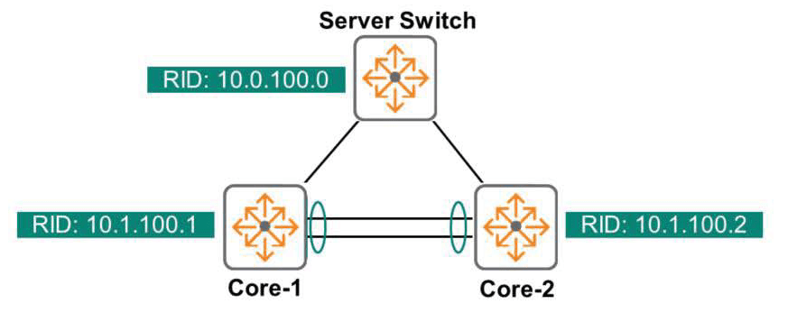
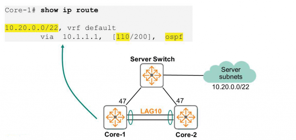
Just as we can see in the topology of the diagram that the Server Switch, Core-1, and Core-2 switches are identified, the routers are identified as 10.0.100.0, 10.1.100.1, and 10.1.100.2.
Administrators can either let the router identify itself, or they can take control and manually assign RIDs.
While automatically assigning RIDs might seem appealing because it eliminates the need for administrator intervention, many engineers prefer to assign RIDs manually for documentation, troubleshooting, or administrative reasons.
The AOS-CX switch determines the router's ID in the following order:.
- If you manually specify the RID, the router function is used.
- If no RID is specified, the Loopback interface with the highest IP address becomes the RID.
- If there is no loopback interface, the RID is the regular non-loopback interface with the highest IP address. Interfaces in the down state are not considered.
The loopback interface is a logical interface that is always operational (unless disabled by the administrator).
This interface is useful for certain processes or protocols that rely on the interface being up. Because the IP address associated with the loopback interface is routable, external devices can communicate with it.
As you operate your network, you will find the Loopback interface useful for scalability, troubleshooting, network management, and more.
How OSPF generally works
The role of a router is to learn about all routes, select the best path, and route packets along that path. To achieve this, OSPF uses a four-step approach. Each step creates a table that is built, maintained, and stored in each router's local memory. The more you understand each step and the tables associated with it, the better you will be able to design, deploy, and troubleshoot OSPF networks.
- Step 1: Building a Neighbor Table – Each OSPF router establishes relationships with its OSPF neighbors.
This information Neighbor Tableis available in . - Step 2: Building a topology database (or LSDB (Link State Database)) – Routers supporting OSPF exchange network prefixes and parameters. This information LSDB tableis saved in .
- Step 3: Creating an OSPF routing table – Routers that support OSPF run the SPF algorithm to obtain the best route to a specific destination. The result is OSPF routing tableSave it to .
- Step 4: Building a routing table called a forwarding table or FIB (Forwarding Information Base) – At this stage, the OSPF internal process returns the result. Routing tableSave it to .
So, shall we take a closer look at each step?
Step 1 – Building a Neighbor Table
First, it introduces itself to its directly connected OSPF neighbors. This is to ensure compatibility. This is done by sending an OSPF "Hello" packet to each OSPF interface.
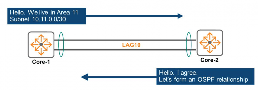
For example, as shown in the figure above, the Core-1 switch will send Hello packets to all interfaces that have OSPF enabled, including LAG10 in subnet 10.11.0.0/30.
""Hello, I'm the Core-1 switch. We currently live in Area 11, and I don't think we need to use security authentication. We're connected to the 10.11.0.0/30 subnet.""
The Core-2 switch will send a Hello packet with similar information to LAG10.
When the criteria match, the OSPF routers recognize each other as neighbors and form an OSPF neighbor relationship.
However, if any of these parameters do not match (usually due to a misconfiguration), the router will refuse to form a neighbor relationship, causing problems for the network.
As shown in the figure above, when each router successfully forms a Neighbor relationship with a peer router to which it is directly connected, each router reflects this information in its Neighbor Table.
※ reference: Here, only a portion of the Hello packet is displayed and explained to convey information about forming a Neighbor relationship.
The actual Hello packet exchanges much more information.
Step 2 – Building a Topology Database
A router shares known subnets with other routers only when adjacencies are fully formed.
“The term ”adjacency” refers to two routers that are physically connected to each other.
It differs from OSPF Neighboring because OSPF Neighbor relationships can be established even between routers that are not physically connected.
Sharing subnets ultimately creates a topology database, listing every single link (subnet), every single router, and how those routers are connected to each subnet.
The way to build it is to send multicast LSA (Link State Advertisement).
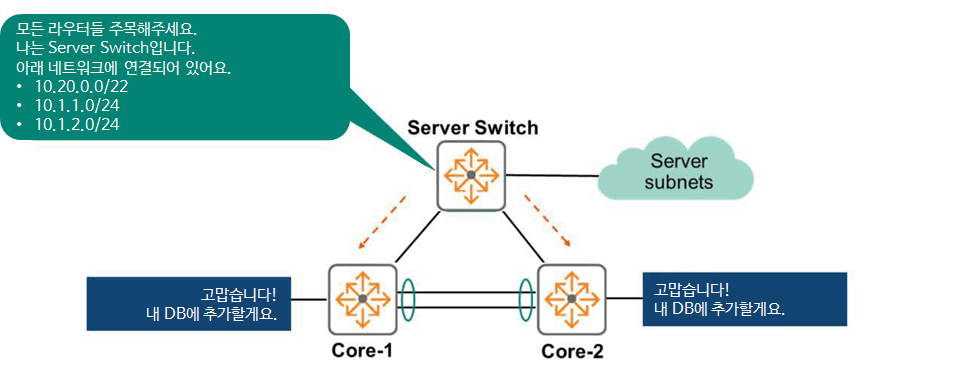
In the above figure, the Server Switch sends LSA messages to all interfaces.
""Attention all routers. I am a Server Switch. I am directly connected to the following networks: 10.20.0.0/22, 10.1.1.0/24, and 10.1.2.0/24.""
All other OSPF routers receive these LSAs and add the information to their topology database.
Soon, every router will receive LSAs from all other routers. This means that each router will have a complete topology database. In other words, it's a database that represents a diagram like the one shown above in numerical form.
Therefore, all OSPF routers have the same topology database.
In the example above, the Server Switch advertises only the Server Subnet it is directly connected to, as this is all the networks it currently knows about. However, if the Server Switch receives an LSA from another router, it will also announce the route.
A router advertises its entire topology database to all other routers.
That's why topology databases are also called Link-State Databases (LSDBs).
Step 3 – Building the OSPF Routing Table
In the figure below, there is only one topology, but the location and connections of each router within that topology are unique.
Therefore, the goal of each router is to determine the best path for each link within the topology.
The way to determine this path is to run the SPF (Dijkstra) algorithm on a topology database, i.e. a Link-State Database (LSDB).
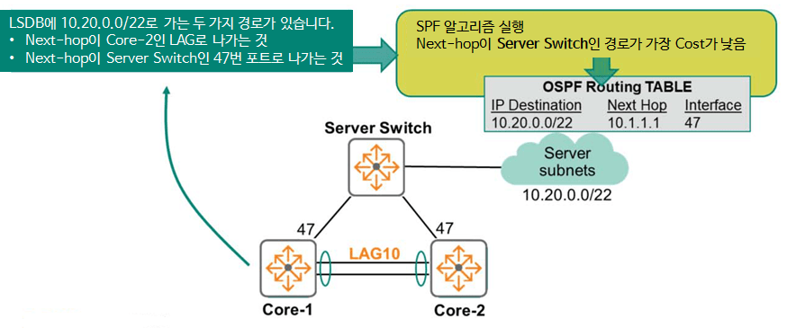
For example, the SPF algorithm on the Core-1 switch analyzes the topology database and determines that the path to the destination 10.20.0.0/22 can be either ① by routing the packet from LAG10 to go through Core-2, or ② by going out port 47 to go through the Server Switch.
The algorithm considers the cost (based on bandwidth) associated with each route and selects the route with the lowest cost (fastest) path. This optimal route is then added to the routing table.
Step 4 – Publish the best route to the routing table.
The best route calculated by OSPF is published in the routing table (FIB, Forwarding Information Base).
In the above figure, the best path for Core-1 to reach the destination (Server Subnet) is through the Server Switch.
So, we've gone through the basic operation of OSPF step by step.
So, let's learn more about Neighboring.
OSPF – Neighboring
Hello message
Directly connected OSPF routers send Hello packets to ensure bidirectional communication and to automate fault detection. By default, these packets are sent every 10 seconds to the multicast IP address 224.0.0.5, a multicast address reserved for the purpose of sending a "Attention all OSPF routers!" message. The mapped MAC address is 01:00:5E:00:00:05.
All Layer 2 switches broadcast packets. FloodingAnd because OSPF sends multicast frames on all ports in the broadcast domain, all directly connected routers exchange Hello, which is the first packet transmitted in the OSPF exchange process.
Another primary purpose of the Hello packet is to create and maintain a Neighbor table.
Only peers that are configured to be compatible form a Neighbor relationship.
They must agree to be on the same subnet and have the same subnet mask. They must also be in the same region and agree on the region type. Furthermore, the timer (OSPF Hello timer: 10 seconds) must match and they must be configured to use the same authentication type.
To check the Hello interval, you can use the “show ip ospf neighbor detail” command.
Core-2# show ip ospf neighbor detail
Neighbor 10.11.100.1, interface address 10.11.0.1 ------------------------------------------------- Process ID 11 VRF TABLE-11, in area 0.0.0.11 via interface vlan110 Neighbor priority is 1, State is FULL DR is 10.11.0.1, BDR is 10.11.0.2 Options is 0x42 Dead timer due in 00:00:30 Retransmission queue length 0 Time since last state change 00h:02m:39s
On AOS-CX switches, the Hello interval is 10 seconds, but you can change the interval from 1 second to 65553.
Switch(config)# interface <interface-id>
Swtich(config-if)# ip ospf hello-interval <seconds>
The Dead Interval is the time interval after which a neighbor is declared dead. It is typically four times the Hello Interval. This value must also match to establish a Neighboring relationship.
OSPF Neighbor Status
OSPF uses a finite state machine (FSM) to handle neighbor state transitions between routers when certain conditions are met. This process can be divided into two main steps.
- Setting adjacency between neighbors
- OSPF database synchronization
In a broadcast network, database synchronization occurs only between the Designated Router (DR) and the DROTHER router (a router that is neither a DR nor a BDR), and between the Backup Designated Router (BDR) and the DROTHER router.
That is, DROTHER routers establish a Neighbor Adjacency and maintain a 2-WAY state (meaning a stable state), but do not synchronize the database.
As an example in the figure below, let's assume that two core switches are attempting to become OSPF neighbors over a broadcast network.
Neighbor Adjacency Settings
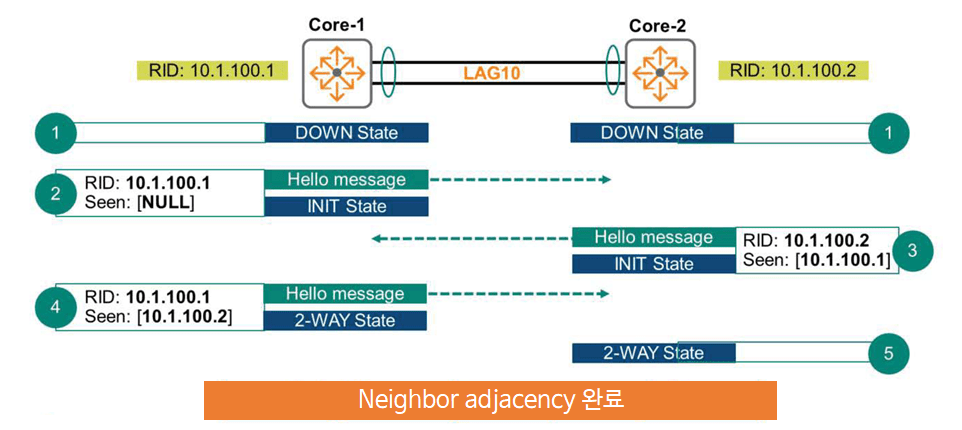
- Core-1 and Core-2 start with the Neighbor status as Down.
- Core-1 switches to the INIT state when sending its first hello message. This message includes the router ID = 10.1.100.1. The hello message includes a Seen field. This field is used by the Core-1 switch to receive hello messages. Since this is the first hello message, this field is set to NULL.
- Core-2 receives Core-1's Hello message and forwards a response message indicating that it has seen the message and is compatible. Core-2 switches to the INIT state as well.
- The Core-1 switch receives the Hello message again and switches to the 2-WAY state. It sends the Hello message to the Core-2 switch again, but this time including the Router ID and Seen fields.
- The Core-2 switch receives this message and transitions to the 2-WAY state.
Here, this network only has two devices: the Core-1 switch and the Core-2 switch. So, we'll proceed with the database synchronization process.
OSPF database synchronization
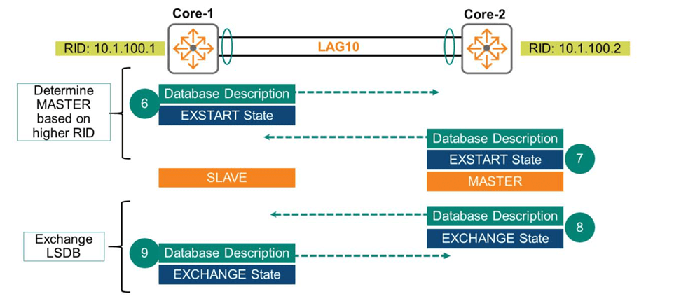
6. The Core-1 switch initiates the synchronization process by sending a Database Description packet. The switch transitions to the EXSTART neighbor state.
7. The Core-2 switch performs a similar process. It sends a Database Description packet and transitions to the EXSTART state. The purpose of the EXSTART state is to determine which switch will become the MASTER of the link based on the highest Router ID. The MASTER's role is to determine which switch will initiate the database exchange process. This role has no relation to the DR/BDR and is dedicated to exchanging the Link-State Database (LSDB).
8. When the Core-2 switch transitions to the EXCHANGE state, it sends another Database Description packet. The Core-2 switch now shares the Summary of the LSDB contents with the Core-1 switch.
9. The Core-1 switch also sends a Database Description packet and transitions to EXCHANGE state while sharing the LSDB with the Core-2 switch.
After sending and receiving several packets in EXCHANGE state, each router has a summary of the other's entire LSDB. They compare the information received with each other and request any missing information in the next step.
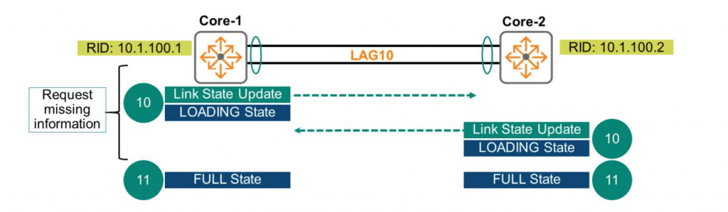
10. Core-1 and Core-2 switches request missing information using Link State Update (LSU) packets. The peer receiving the request responds by sending the requested database information. Both switches transition to the LOADING state.
This LOADING state exchanges the actual routing information.
11. When both the Core-1 and Core-2 switches have no more information to exchange, they transition to the FULL state. At this point, both devices have the same Link-State Database (LSDB).
“You can check the OSPF neighbor status using the ”show ip ospf neighbors” command.
Core-1# show ip ospf neighbors Neighbor ID Priority State Nbr Address Interface --------------------------------------------------------------------------------
10.1.100.2       1         FULL/DR 10.11.0.2            LAG10
So today we briefly looked at the most commonly used OSPF routing protocol in theory.
In the next post, we will go into more detail about OSPF operation and how it works.


