Previous PostWe learned about the default gateway in . An endpoint can only have one default gateway, and that can be a single point of failure.
As you can see in the figure below, if Core-1 fails, all hosts that use Core-1 as their default gateway, including PC-1, will be isolated.
How should we deal with this situation?

You can also add another default gateway for redundancy. This may seem like an easy solution, but it may not be.
The default gateway information for each endpoint can be manually configured or obtained via DHCP.
If Core-1 fails, you will need to manually update the new default gateway information or reconfigure the DHCP scope, then have all end users disconnect from the network and reconnect to receive the new information from DHCP.
C:\> ipconfig /release
C:\> ipconfig /renew
The above method does not seem very efficient and does not seem to have much scalability or convenience.
So what other alternatives are there?
FHRP (First Hop Redundancy Protocol)
A practical solution to this problem would be to use some form of First Hop Redundancy Protocol (FHRP) to address the issue at the network level, rather than at the endpoint level.
This is for endpoints using a coordinated gateway solution. dynamic stabilityAdd .
No changes to endpoint IP configurations, no DHCP modifications, and no end-user disruption – completely automated!
“Resiliency” is a term that refers to the ability of a network to cope with changes or failures.
The FHRP solution is implemented on two or more physical routers. Single Coordinated GatewayCreates.
Two or more of these physical routers are one VIP (Virtual IP) addressIt presents itself to the endpoint as a virtual device with a VIP, and this VIP becomes the endpoint's default gateway address.
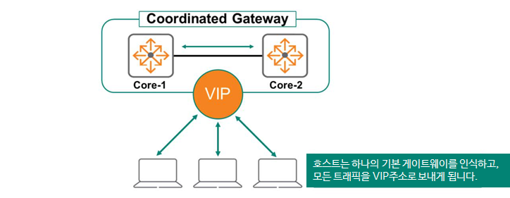
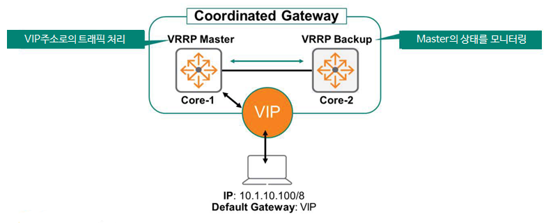
Typically, the Primary Routing Device acts as the default gateway, forwarding traffic to endpoints. The Secondary Device monitors the status of the Primary Device.
If the primary device fails, the secondary device will take over. The secondary device will assume the primary role and VIP address and forward endpoint traffic.
From the endpoint's perspective, the virtual IP address remains available. Because the default gateway address remains unchanged, the end user's network remains uninterrupted.
VRRP (Virtual Router Redundancy Protocol)
RFC 5798 defines Virtual Router Redundancy Protocol (VRRP), a standard FHRP that allows two or more routing devices to provide gateway redundancy to an endpoint.
VRRP uses a master-standby architecture. Only one gateway forwards traffic addressed to the VIP address. This primary forwarding device is called the master, and the non-forwarding devices serve as backups.
VRRP instance
ArubaOS-CX can deploy multiple instances of VRRP. It also allows you to adjust load balancing across VLANs, as shown in the figure below.
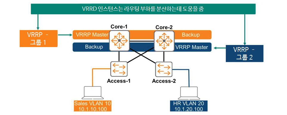
Each instance has a unique Virtual Router ID (VRID) number, and AOS-CX indicates the group ID as shown in the figure above. VRRP instance 1 provides VLAN 10, and VRRP instance 2 provides VLAN 20.
Switch Core-1 is the master and active forwarder for VLAN 10, and Core-2 is in standby state.
On the other hand, Core-2 is the master for VLAN 20, and Core-1 is the standby.
This way, we can provide load balancing capabilities for routing.
VRRP instance capacity
This instance is also called a Virtual Router ID (VRID) in VRRP, and the number of VRIDs supported varies depending on the switch's capacity. In ArubaOS-CX, you can check the switch's capacity using the "show capacities vrrp" command.
Switch# show capacities vrrp
System Capacities: Filter VRRP Value ---------------------------------------------------------------------------
Maximum number of unique IPv4 VRRP VRIDs configurable between 1 to 255 8
Maximum number of VRRP IPv4 addresses supported 1024 Maximum number of VRRP IPv4 addresses supported per virtual router 16 Maximum number of VRRP IPv4 virtual routers supported per port 8 Maximum number of VRRP virtual routers supported 256 <<< >>>
VRRP Master Selection
VRRP members exchange multicast advertisement messages using the IP address 224.0.0.18 and protocol 112 to elect a master gateway.
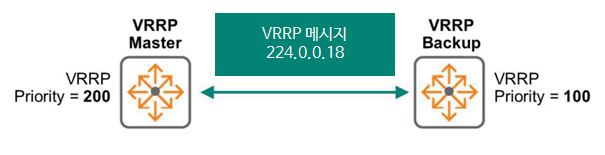
To specify master selection, set a priority value from 1 to 255. The gateway with the highest priority (higher numbers indicate higher priority) will be selected as the master. If priorities are tied, the gateway with the highest IP address will be selected.
In ArubaOS-CX, the default priority is set to 100.
VIP address (Virtual IP)
VIP, or virtual IP address, is the result of gateway coordination. Typically, each individual physical gateway is assigned a unique real IP address. VIP addresses must also be unique.
As you can see in the image below, the master gateway is assigned a physical IP address of 10.0.10.1, the backup gateway is assigned 10.0.10.2, and the VIP address is 10.0.10.3.
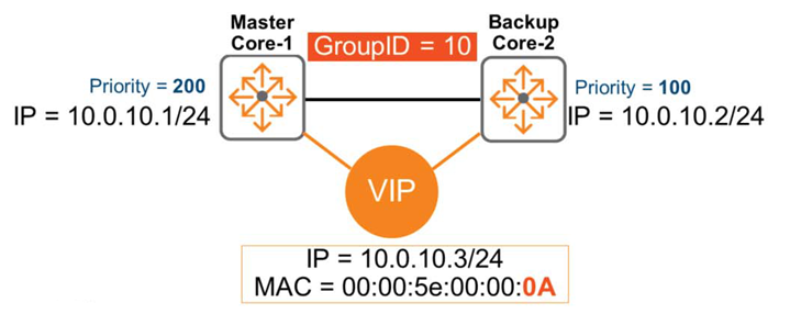
Each VRRP instance has a unique VRRP address. In the diagram above, 10.0.10.3 might be the VIP address of instance 10 used in VLAN 10. And instance 20 used in VLAN 20 might use 10.0.20.3 as the VIP address.
Let's check if this VIP address is configured as the default gateway for the endpoint.
First, the endpoint forwards traffic to the VIP address. The VRRP master receives and routes these packets. If the master device fails, the backup device takes over. The endpoint device does not learn about the router's physical IP address (e.g., 10.0.10.1, 10.0.10.2).
A vMAC (virtual MAC address) is automatically assigned to the VIP. According to the standard, the MAC address in the above figure is 00:00:5e:00:00:xx Here it is xx가 VRIDIt will be shown as, in the picture 0AA virtual MAC address is created.
※ In hexadecimal 0Ais in decimal 10It represents.
Therefore, the endpoint learns about the vMAC address 00:00:5e:00:00:0a for the default gateway address 10.0.10.3 and adds it to the ARP table.
How VRRP Failover Works
The figure below shows a scenario where two Core switches are running VRRP.
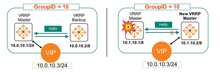
Core-1 has a higher priority and assumes the role of VRRP Master. Core-2 acts as VRRP Standby and continuously monitors the status of Core-1 through the keep-alive mechanism.
The endpoint forwards traffic to the VIP address 10.0.10.3, which is being served by the VRRP master.
What happens if Core-1 fails here?
The standby device detects that the master server has failed and is down because it stops receiving keep-alive messages. The standby device then takes over as the new master and begins forwarding traffic to VIP 10.0.10.3.
VRRP Preemption
Continuing from the above, we see that Core-1 failed and Core-2 took over as the new master. So what happens when the failover is complete and Core-1 is back online?
This time will vary depending on how you configure VRRP preemption.
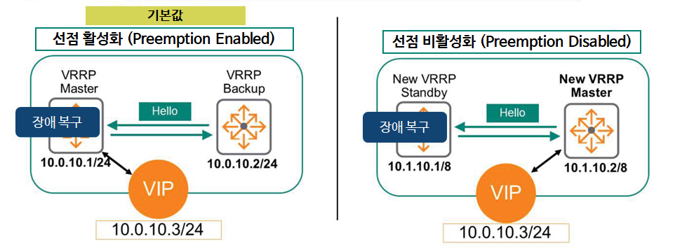
If preemption is enabled, Core-1 resumes its original Master role and Core-2 returns to the Standby role – this is the default setting in ArubaOS-CX.
This is administratively beneficial because, assuming all devices are online and operating normally, the same router device will always be the master. This can be especially important when using multiple VRRP instances. If one master fails, the remaining devices must shoulder the traffic load for all endpoints.
If preemption is disabled, Core-1 will not revert to its original Master role. Core-2 will retain the Master role, and Core-1 will assume the Standby role.
To disable preemption here, you must manually enter the command “no prempt”.
Disabling preemption will prevent you from taking advantage of the above benefits. However, some administrators are concerned about the intermittent disconnections that can occur during the preemption process, when the router (gateway) reverts to its original role, and so they disable preemption.
However, you don't have to worry about this because ArubaOS-CX devices are designed for high performance.
VRRP and MSTP coordination
In a previous post we said LoopI have learned about it and how to prevent it. Spanning TreeWe also learned together in these scenarios: MSTPCoordination is required between the root bridge and the VRRP master to ensure proper traffic forwarding.
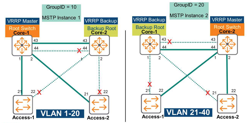
For example, let's take a look at the picture above.
The Core-1 switch is configured as the Root Bridge for MSTP Instance 1, supporting VLANs 1 through 20. Additionally, the Core-1 switch is configured as the VRRP master for the same VLAN range (VLANs 1-20).
If Core-1 fails, Core-2 becomes the new VRRP master and the new root bridge for Instance-1.
So today we learned about VRRP.
Among Layer 3 features, VRRP is one of the important features in a redundant configuration environment.
Configuration example
Now, let's look at an example of actually configuring it on an ArubaOS-CX switch.
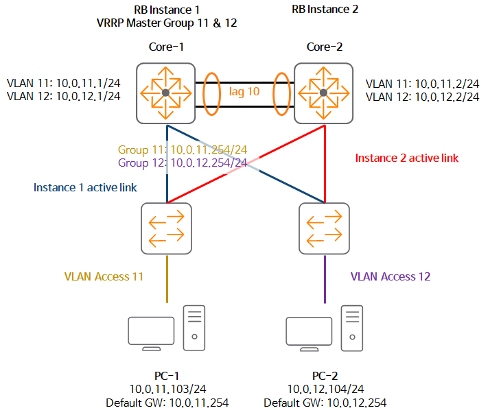
Let's configure the scenario as above.
1. Configure VRRP on the VLAN interface of the Core-2 switch.
Core-2(config)# interface vlan 11 Core-2(config-if-vlan)# vrrp 11 address-family ipv4
Core-2(config-if-vrrp)# address 10.0.11.254 primary
Core-2(config-if-vrrp)# no shutdown
2. Check VRRP information.
Core-2# show vrrp interface vlan11
VRRP is enabled Interface vlan1111 - Group 11 - Address-Family IPv4
  State is MASTER
  State duration 01 mins 17.300 secs
  Virtual IP address is 10.11.11.254
  Virtual MAC address is 00:00:5E:00:01:0B Advertisement interval is 1000 msec
  Version 2
  Preemption is enabled min delay is 0 sec
  Priority is 100
  Master Router is 10.11.11.2 (local)
  Master Advertisement interval is 1000 msec Master Down interval is 3609 msec
Core-2(config)#
3. Configure it on the Core-1 switch as well.
Core-1(config)# interface vlan 11
Core-1(config-if-vlan)# vrrp 11 address-family ipv4
Core-1(config-if-vrrp)# address 10.0.11.254 primary
Core-1(config-if-vrrp)# no shutdown
4. Set the priority to 254 to set the Core-1 switch as Master.
Core-1(config-if-vrrp)# priority 2545. Check the VRRP configuration of Core-1 (same MAC address as Core-2's vMAC address).
Core-1(config)# show vrrp interface vlan11
VRRP is enabled Interface vlan11 - Group 11 - Address-Family IPv4
  State is MASTER
  State duration 12.501 secs Virtual IP address is 10.11.11.254
  Virtual MAC address is 00:00:5E:00:01:0B
  Advertisement interval is 1000 msec Version is 2
  Preemption is enabled
   min delay is 0 sec Priority is 254 Master Router is 10.11.11.1 (local) Master Advertisement interval is 1000 msec Master Down interval is 3007 msec
6. Configure VRRP for VLAN 12 in the same way.
Core-1(config)# interface vlan 12
Core-1(config-if-vlan)# vrrp 12 address-family ipv4
Core-1(config-if-vrrp)# address 10.0.12.254 primary
Core-1(config-if-vrrp)# no shutdown
Core-2(config)# interface vlan 12
Core-2(config-if-vlan)# vrrp 12 address-family ipv4
Core-2(config-if-vrrp)# address 10.0.12.254 primary
Core-2(config-if-vrrp)# no shutdown
7. Verify VRRP information for two VLANs.
Core-2# show vrrp brief
vlan11 11 IPv4 100 3647 NY BACKUP 10.11.11.1 10.11.11.254 vlan12 12 IPv4 100 34 NY BACKUP 10.11.12.1 10.11.12.254
We have looked at an example of configuring VRRP like this.
It would be a more useful exercise to configure an actual lab and conduct a failover test, and see how to get the MAC address from the ARP table and whether there are any issues with gateway communication.