Today's demand for network availability is relentless.
Customers need networks that operate 24/7, 365 days a year, and HPE's VSX technology provides a solution to this problem.
HPE Aruba Networking's VSX technology is a virtualization technology for data center and core switches running on the AOS-CX operating system.
This solution is like switches in critical areas. Acts as a single virtualized switchSo on the network Redundancy and resilienceAdd .
In this article, you will learn how VSX can help you achieve better performance, resiliency, and reliability in your data center.
Switch Virtualization Solution
HPE Aruba Networking VSXis a virtualization technology that runs on the AOS-CX operating system.
This solution is for switches in critical areas. Acts as a single virtualized switchLet's do it.
Configuration synchronization is a feature of this VSX solution that synchronizes from the Primary switch to the Secondary switch.
VSX is a two-switch Virtualizing the Control PlaneSo that it functions as a single device at L2 and as an independent device at L3. Datapath perspectiveIn , each device independently performs forwarding to determine how to handle traffic.
Some forwarding databases, such as the MAC forwarding database and neighbor table, are synchronized between the two devices using the proprietary VSX control plane. Each switch independently builds some forwarding databases.
HPE Aruba Networking Virtual Switching Framework (VSF) allows multiple switches of the same model to be Acts as a single virtual deviceHPE Aruba's Networking stacking technologyVSF provides fast failover, scalability, ease of management, and high availability.
The VSF fabric has the following characteristics:.
- The management module of the Conductor switch provides One active management plane and one active control planehave
- The conductor proxies the control plane to the standby member.
- Both members of the fabric participate in the forwarding plane.
- The interface modules of the two members are combined as one large switch connected by a VSF link.
HPE does not recommend using VSF in live data center network environments.
Instead, VSF can be used to stack multiple OOBM switches together.
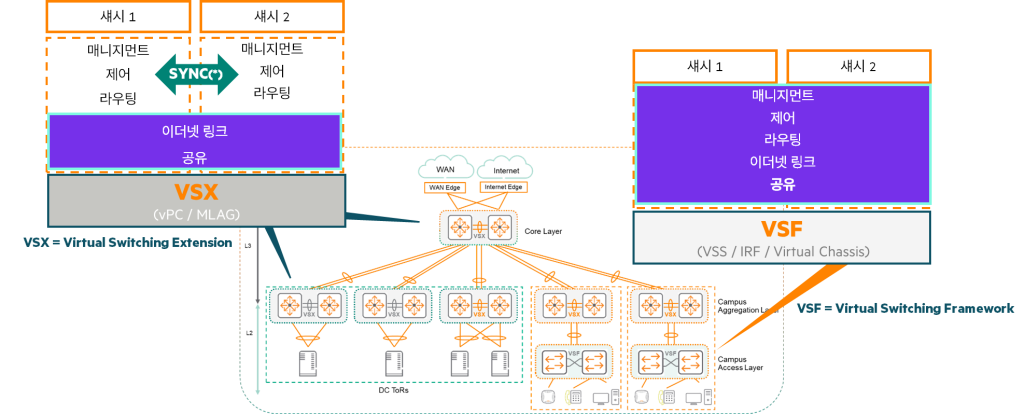
HPE Switch Virtualization Solutions: The Difference Between VSX and VSF
HPE has designed two primary switch virtualization solutions to address the various layers and requirements of your network:
- VSX (Virtual Switching eXtension)
- VSF (Virtual Switching Framework)
The differences between each solution can be summarized in the table below.
| characteristic | VSX (Virtual Switching eXtension) | VSF (Virtual Switching Framework) |
|---|---|---|
| Main application layer | Core and Aggregation Layer (Data Center/Campus) Core sections where large amounts of traffic are concentrated and high stability is required | Access Layer (Campus) The switch where the end user equipment is connected |
| How to set up | Manual settings (strict control) Administrator manually sets the feature on both switches | Plug and Play (automatic join) |
| Control/Management Plane | Dual control/management plane (synchronization option) Each switch has its own control and management functions, but can be synchronized for specific functions when required. | Single active control/management plane Multiple switches act as a single virtual device, providing simplicity of management. |
| Traffic handling | Active-Active (L2, L3 unicast, L3 multicast) It acts as a single device to other devices on the network. | (All Fabric members participate in forwarding) |
| Port default | Disable, L3 operation | activate, L2 operation |
| Upgrade | Even during software upgrades Virtually zero downtime (provides high availability) | (Fast failover, providing high availability) |
HPE offers two powerful virtualization technologies, VSX and VSF, to meet the diverse needs of networks, each designed to deliver optimal performance and stability at specific network layers.
Advantages of VSX
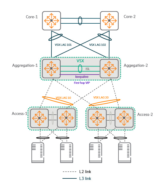
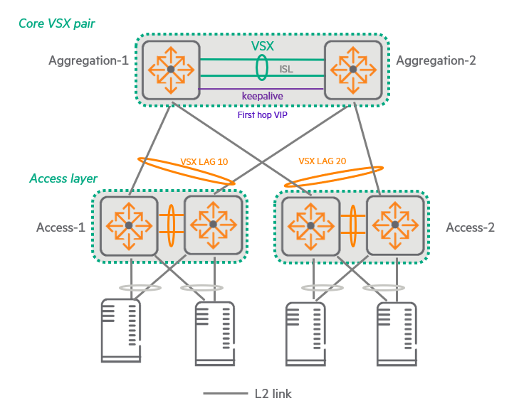
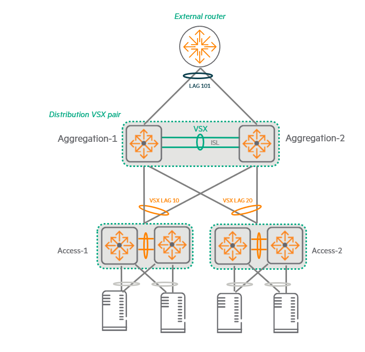
Here is an example of a 3-tier topology recommended by HPE.
In this topology Deploy VSX in the access and aggregation layerdo.
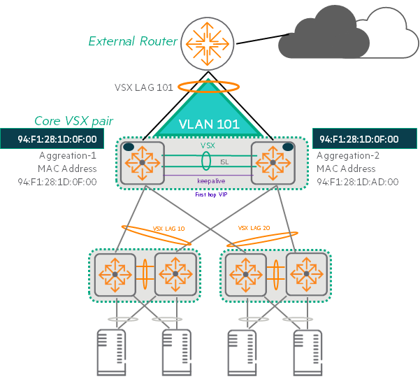
If your topology requires it, you can also deploy VSX at the core layer, but typically you'll want to keep your redundant core switches completely independent.
Dual Control Plane provides maximum resiliency and software upgrades with near zero downtime.
At the same time, VSX supports the features that the administrator chooses to synchronize. Integrated managementAllows.
VSX and Link Aggregation (LAG)
The VSX pair is Connect to a switch in the access layer using link aggregation (LAG) across both VSX switches.It will work.
This type of LAG Multi-chassis, distributed, or VSX LAGIt is called.
Since the switches at the access layer do not do routing, this VSX LAG Operates at L2do.
The VSX pair in the Aggregation layer acts as the Default Gateway for the Access VLAN.
These L2 LAGs are used in link redundancy environments. MSTP1 or RPVST2Eliminate the need fordo.
These are Provides loop-free pathsThis ensures that all links in the aggregation switch are active.
Configuring a LAG-based topology is simple, and it is robust even if one link fails. Failover occurs very quicklydo.
VSX and L3 connection
The VSX pair is L3 link to core switchhas.
Each VSX switch has a ROP3 or L3 VLAN interface assigned to that port4through each switch Connect independentlyYou can do it.
Alternatively, both VSX switches can be connected together to each core switch via a VSX LAG.
This LAG operates at L2 and is connected to one or more Virtual Switch Interfaces (VSIs).
Whichever option you choose, the VSX is ECMP5Through Active-Active L3 Routingand supports efficient paths for unicast traffic.
The last option (a combination of L3 ECMP and VSX LAG) is High fault-tolerant systemBuild.
Active Gateway feature
The VSX pair is an access VLAN. Default gateway roleIt is important to remember that:.
For this purpose, the VSX pair Active Gateway FunctionUse .
This feature allows each switch to Act as the default gateway for each VLAN using a shared virtual IP address and virtual MAC address.Let's do that.
And VRRP6 or HSRP7It eliminates the need for .
The Active Gateway feature is simple to configure and relies on VSX operation. It does not incur any additional protocol overhead.
It also supports redundancy for DHCP relay functionality.
VSX Management Plane Synchronization
VSX uses a dual management plane, but these management planes are Supports synchronizationdo.
This synchronization is an innovative feature of AOS-CX. Database-centric design Thanks to this, it is partially possible.
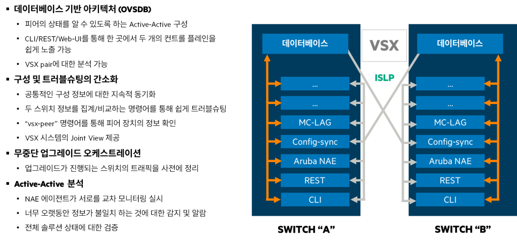
Key Principles and Benefits of VSX Synchronization
- Peer-to-peer status awareness: Switches within a VSX pair can synchronize parts of their databases, allowing each switch to actively forward traffic while Accurately recognize the status of other switches (peers)You can do it.
- Simplicity of management: VSX easily exposes both control planes to administrators and business applications through CLI, REST interface, and web user interface (UI). Simplicity of managementThis not only simplifies management, but also provides a redundant switch pair across the Analytics are possibleLet's do it.
- Selective sync: Administrators can control interfaces and VLANs. Select specific components to synchronize between VSX pairsYou can do this. This will keep the settings for that component in sync, so that the switch pair Makes configuration easier do Minimize the possibility of errorsdo.
- Easy setup comparison: The administrator aggregates and compares information about multiple components from both switches.
showYou can use commands, You can quickly find mismatched settings. - Provides a unified view: Also, many commands
vsx-peerYou can add options to view information about both local and peer switches, so that you can see information about the VSX system. Simple and integrated viewin the file. - Supports non-stop live upgrades: VSX sync is Coordinate hitless live upgradesIt also helps when one switch needs to be upgraded, the other switches will be aware of this and will redirect traffic from the switch being upgraded to the other switch. Move activelyYou can do it.
HPE Aruba Networking NAE (Network Analytics Engine) Integration
Each VSX pair's switch has its own NAE that stores sensor values locally.8 Maintain the agent. NAE recognizes VSX.
- Mutual monitoring: Each member's agent connects to the other member's database. Cross-monitoringcan detect inconsistencies. For example, each NAE agent monitors the number of objects in the primary and secondary switch databases.
- Health Verification: If synchronization is working correctly, the number of objects should be the same. For example, an alert may be triggered if the number of objects in the primary database is 20% more than in the secondary database for more than 5 minutes. Active-Active Analysishelps to verify the health of the entire solution.
VSX components
VSX is a technology that significantly improves network stability and efficiency by overcoming the limitations of conventional LAG (Link Aggregation Group).
Distributed LAG (Multi-Chassis LAG)
As previously introduced, VSX Link aggregation technologySupports .
This is two or more links Tie across two switches This is done by creating a single logical interface called LAG.
The typical IEEE 802.3ad standard is limited to aggregating links only within a single switch or device.
But the VSX feature is Unique technologyWe overcome these limitations by using .
VSX is Supports link aggregation for links spanning multiple switches within the same VSX stack.do.
These two switches are connected by a dedicated link called an Inter-Switch Link (ISL).
Node-level redundancy
Additionally, VSX provides redundancy in case one switch in the network fails. Node level (switch itself) redundancyin the file.
Downstream devices (servers or other switches connected to the downstream network) must be configured with 802.3ad LAG interfaces.
Although the LAG is connected to two separate devices (VSX switches), from the downstream device's perspective, they are One single deviceIt looks like.
Downstream devices Any device that supports LACP (802.3ad)It could be.
Primary/Secondary and Settings Synchronization
In a VSX environment, one switch Primary The other switch plays a role Backup (Secondary) It plays a role.
if config-sync When you enable the feature, Synchronize the settings of the primary switch to the secondary switchIt will work.
But the important thing here is Not all settings are synchronizedno see.
The administrator VSX-syncThrough Synchronize only manually activated elementsIt will work.
ISL (Inter-Switch Link): The lifeline between VSX switches.
An ISL (Inter-Switch Link) is a Layer 2 interface established between two VSX peer switches.
This link must be configured so that the two VSX switches are directly connected to each other.
Key features of ISL:
- Datapath: It performs the role of forwarding actual user and service traffic.
- Control Path: Used to exchange VSX protocol messages and synchronize management plane (e.g., configuration, state information)
ISL Configuration Recommendations:
- Link Aggregation (LAG): Although it can be configured as a single physical link, HPE has Up to 8 physical links are grouped together to form a LAG.I recommend doing so.
- Link speed: All links within a LAG are rated at 10Gbps, 40Gbps, or 100Gbps. Same speedIt should be.
To ensure sufficient bandwidth in the data path, it is generally recommended to use multiple 40Gbps or 100Gbps links. - Ports and Media: ISLs utilize the plain ports of member switches and can use any media type (e.g., copper, fiber). Fiber optics also allows for long-distance connections, depending on the fiber or transceiver type.
Features of the ISL interface:
- VLAN membership: Basically within the device Member of all VLANsno see.
You can change this via the CLI, but any VLANs that are passed through the VSX LAG must also be included in the ISL. - Traffic forwarding: In the data path, traffic is different from VSF. Without additional encapsulation (natively) It will be forwarded.
- Policy Control: As with other interfaces on the switch, QoS (Quality of Service) and ACL (Access Control List) policiesYou can control traffic by applying it to the ISL (be careful not to block essential traffic).
- DSCP preservation: ISL is Preserve DSCP (Differentiated Services Code Point) remarkingFor example, if the LAG link on the local switch fails and traffic is sent over an ISL, the packets retain the DSCP value they had when originally sent over the LAG. However, the ISL interface on the other peer switch must be configured to trust the DSCP setting of the received frame.
ISLP (Inter-Switch Link Protocol):
ISLP is a protocol that runs on top of ISL and is responsible for the core functions of a VSX pair.
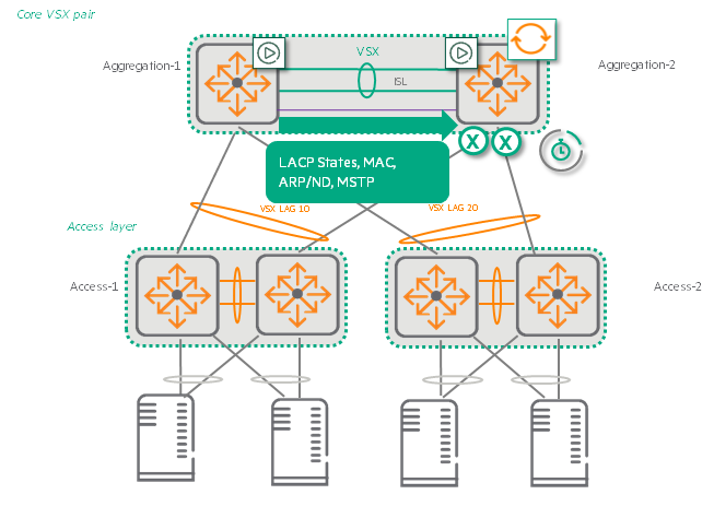
Initial and ongoing synchronization:
When you first configure a VSX pair, synchronize the switches.
After that LACP status, MAC table, ARP table 및 Settings informationContinuously synchronizes.
Peer status detection:
Basically every second Periodically exchange hello packetsDetects the status of the peer.
The default dead interval is 20 seconds. If a hello packet is not received during this time, the peer is considered down. Start split detectiondo.
Fast failover:
Although the dead interval may seem long, each VSX switch maintains its own control plane.
If one switch goes down, the VSX LAG links on that switch will also go down immediately and traffic will be redirected to other peer switches that are already actively forwarding it. Immediate failoverThe service will continue without interruption.
ISL link down detection:
Typically, if all physical links in an ISL link are down for the hold time (default 0 seconds), the ISL link is considered “down” and split detection is triggered.
Keepalive
In addition to ISL, in the VSX environment Keepalive connectionYou need to configure it on each VSX switch to check the status with other switches.
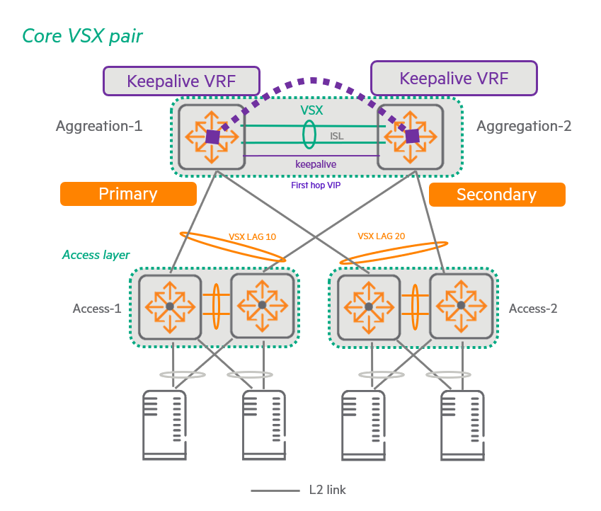
The necessity and role of Keepalive (KA)
Protection in case of ISL failure:
If an ISL goes down, each VSX peer uses KA communication to check if the peer is still up (it is just not reachable through the ISL).
That is, the VSX pair Split-brain Used to detect if a state has been entered.
Handling split-brain scenarios:
If KA communication indicates that the peer is still operational, The main VSX switch keeps its VSX LAG link active.do.
on the other side The secondary VSX switch forces its own VSX LAG link down.I'll order it.
The primary switch is selected based on the role settings configured by the user when setting up the VSX.
If you configure the switches to have the same role, Lowest MAC addressThe switch with has priority.
This mechanism prevents split-brain situations where both switches are mistakenly active, causing network loops or traffic loss.
Keepalive Connection path and settings
- Independent path: Peers Routed networkExchange keepalive packets through .
This path may be a direct L3 link or an indirect link through an upstream L3 network. - ISL Bypass: The important thing is that the keepalive packet To avoid passing through ISL That is what must be done.
This is to ensure that the status between peers can be independently verified even when the ISL itself fails. - Source Interface: For stability, the source of the keepalive packets is loopback interfacecan be set to .
Keepalive Technical characteristics of the packet
- UDP based: Keepalive packets use UDP (User Datagram Protocol).
- Default port: By default it uses port 7678, but the UDP port is configurable.
- Hello Packet Interval: Keepalive hello packets are basically Transmit every secondand this interval can be configured between 1 and 5 seconds.
- Dead Interval: Keepalive Dead interval is 3 secondsand can be configured between 2 and 20 seconds.
If a device does not receive a keepalive packet from its peer within the dead interval time, it considers the peer device to be 'out-of-service' and does not activate the split-brain protection mechanism.
(Since the peer is already considered completely down, no protection mechanism is needed).
Active Forwarding: Optimal traffic flow without going through ISLs.
Active forwarding optimizes forwarding so that traffic is distributed across the core and aggregation VSX pairs. When it flows to any switch and is then forwarded to the access layer, it is processed without crossing the ISL (Inter-Switch Link).Make it possible.
This allows each switch to learn the SVI MAC address of its peer and route on its behalf., Improve network efficiency and performanceI'll order it.
How Active Forwarding Works
- Learning peer MAC addresses: With active forwarding, each VSX switch is associated with a specific Switch Virtual Interface (SVI). MAC address of your peer switchto your own interface Additional MAC addressesIt consists of:.
- Routing-only lookups: This additional MAC address is Performs only lookup function for routingdo.
That is, when the switch receives an Ethernet frame destined for that MAC address, it performs Layer 3 processing on the packets within it and Routing on behalf of peer switchesdo. - Ensuring optimal forwarding paths: This applies to all traffic routed from the core to the access layer. Ensure optimal forwarding pathRegardless of which next hop and link the core selects for a given traffic, when a VSX switch receives a frame destined for the peer switch's MAC address, it processes the packet internally and routes it on behalf of the peer.
- Own traffic and downstream traffic: But the VSX switch When generating traffic on your own or routing traffic downstream, you still use your own MAC address., and does not use additional MAC addresses of VSX peers.
Active Forwarding Configuration and Limitations
- Supported only for SVI: To enable active forwarding, the VSX pair Configure this feature on all SVIs connected to the upstream LAG.Must do.
- example: In the given example, this feature is enabled on interfaces VLAN 101 and 102. This Only SVI supports active forwardingBecause it does.
- Maximum number of VLAN interfaces: As of the time this process was published, the VLAN interfaces that can use active forwarding on a VSX pair are: Up to 16no see.
Active Gateway
The Active Gateway feature is an innovative solution that provides primary gateway redundancy in VSX environments.
Active Gateway is a first-hop redundancy protocol (FHRP) that eliminates the single point of failure of the default gateway service in the access network. This active gateway feature allows a virtual router to act as the default gateway for that network, thereby improving the reliability of the host network. Improved stability and performanceI'll order it.
It is much simpler to configure than VRRP and maximizes data plane efficiency, especially since both VSX switches can actively forward traffic.
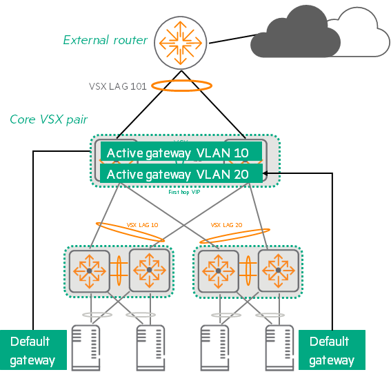
How to Set Up and Operate an Active Gateway
- Using Virtual IP/MAC: To configure this feature, connect the SVI of both VSX switches to Use shared virtual IP addresses (VIP) and shared virtual MAC addresses (VMAC).This VIP/VMAC acts as the default gateway for each access VLAN.
- Traffic Handling: Which switch in the VSX pair receives specific traffic from the access VLAN depends on which link the downstream access switch's Link Aggregation Group (LAG) selects. Whichever switch receives the traffic, that switch routes the traffic to the L3 domain.
- VRRP not required: When you use an active gateway for a specific VLAN, that VLAN has No need for VRRP.
These two functions are mutually exclusive. - Source MAC address: As with VRRP, traffic routed from a VSX peer is routed to a non-VMAC address. Switch interface MAC addressIt starts from .
- VMAC Aging Prevention: Every 3 minutes (not configurable) each active gateway receives a Broadcast a hello packetThis prevents VMAC aging on the access switch. Hello packets transmitted from both peers are forwarded over the same VSX LAG, so there is no problem with the same MAC address appearing on different ports (MAC flapping). These Hello packets are Ethernet packets, not IP, and use HP EtherType (080009 Hewlett-Packard) and a reserved multicast destination address.
Key Differences Between VRRP and Active Gateway
There are several important differences between the Active Gateway feature and VRRP:
| characteristic | VRRP (Virtual Router Redundancy Protocol) | Active Gateway |
|---|---|---|
| Configuration complexity | Requires several configuration options, including the Virtual Router Identification (VRID) of the VLAN, the role of each VRID, the virtual IP address of each VRID, and the advertisement timer. | Only one line of configuration is required per VLAN interface (virtual IP/MAC configuration) |
| Traffic forwarding method | Active-Standby data plane Enabled; only the active router that is the VRRP owner routes traffic. | Both devices forward traffic (Active-Active Similar) |
| Protocol type | Open standard (IEEE standard) | Features specific to HPE AOS-CX switches |
| overhead | The presence of overhead in the VRRP protocol itself | Depends on VSX operation, No additional protocol overhead |
| purpose | Default gateway redundancy | Default gateway redundancy and Optimizing efficient traffic distribution in VSX environments |
VSX Switch Reboot and Initial Sync Process
When a switch reboots in a VSX environment, it's important to minimize network traffic disruption and maintain database consistency. This process involves the following steps:.
Initial Sync Phase
VSX nodes synchronize their peers' state every second via the Inter-Switch Link Protocol (ISLP).
Key information that is synchronized includes:
- Learned MAC address
- LACP status
- MSTP status
In a VSX scenario, even though all traffic from core to access flows through only one switch, other switches will learn ARP/ND (Neighbor Discovery) information through the VSX peer. This does not affect the normal data path-based learning functionality.
Scenarios where a VSX is split and then rejoined (e.g. periodic synchronization) will resume after bulk synchronization.
IVRL (Inter-VRF Route Leaking)is a technique for “leaking” routing information from one VRF to another VRF.
You can create multiple independent routing tables (VRFs) within a single switch to operate different networks.
Normal VSX synchronization (MAC, ARP tables, etc.) works fine, but, Neighbor information generated through IVRLis not automatically synchronized between VSX peer switches because the IVRL is set on each switch. individually Because it is a working routing mechanism.
When a switch receives a route from one VRF to another via IVRL, that information is not passed to other switches via the VSX synchronization protocol. Instead, each switch Local (own) data pathLearn IVRL Neighbor items through .
Therefore, the neighbor entries generated by IVRL are generated on each switch of the VSX pair. Each one learns againMust do.
Even if IVRL works on one side and a Naver entry is created, the other switch does not receive the information and register it with Naver right away, but rather uses its own IVRL mechanism based on synchronized ARP information, etc. Relearn on your ownYou have to go through the process.
How the VSX Switch Works When Rebooting
When the VSX switch reboots, information about ARP, MAC, and routes is Nothing at allIt becomes.
If the downstream VSX LAG port becomes active before this switch has relearned all information, traffic loss will occur.
To prevent this traffic loss, the VSX LAG on the rebooted switch remains inactive (down) until the LACP, MAC, ARP database, and MSTP status are restored.
The VSX LAG learning process consists of two stages:
1. Initial sync phase:
LACP state, MAC address/ARP tables, and potentially MSTP state are downloaded from the forwarding switch to the newly rebooted switch.
- Download process: Steps for the rebooted switch to download all LACP, MAC, ARP, and MSTP database entries from the VSX peer via ISLP.
- Timer: This initial synchronization timer is Settings are not possible, as much time as is required to download database information from peers.
2. Link-up delay phase: Mechanism to prevent traffic loss when VSX switch reboots
This step is to wait for the rebooted switch to process the downloaded information stably and fully rejoin the network.
The system downloads the items Installed on ASICAnd, router adjacency relationship with core node9and set it up, Learning the upstream pathdo.
This step linkup-delay-timer It can be configured by command. The default is 180 secondsno see.
If you have a lot of MAC addresses, ARP tables, or routing tables, you may want to consider setting the link-up delay timer. Up to 600 secondsYou can set it up to .
If both switches reboot
When both VSX switches are rebooted, both switches will need to relearn the LACP state, MAC address table, and ARP table. The link-up delay timer is not used.
- Excluding upstream LAG: During link-up delays, it may be necessary to quickly establish upstream router adjacency relationships<=.
At this time Exclude upstream LAG from link-up delay rangeMust do. - Exclusion Command:
linkup-deal-timer exclude lag-listIdentify the LAGs to exclude by running the command.
On a VSX switch, you entered one or more of the following commands:,
If you do not input on other VSX switches, the two switches ARP entries are out of sync.
clear ARP: This is a command to clear the ARP table.interface VLAN: This command enters VLAN interface configuration mode.shutdownfor a VLAN: This command terminates a specific VLAN.no shutdownfor a VLAN: This command re-enables a specific VLAN.
Multi-Chassis LAG (VSX LAG)
VSX LAGis two or more links Tie across two switches It is a technology that forms a single logical interface, LAG.
This provides redundancy and bandwidth expansion with upstream/downstream devices.
especially local optimizationMaximizes network performance by ensuring that traffic is delivered through the most efficient path without unnecessarily traversing ISLs.
Key Features of VSX LAG
- Recognize as a single device: From the perspective of the upstream or downstream partner devices that make up the VSX pair and LAG, the two switches A single device with one Peer IDIt looks like.
- Port Speed: All ports belonging to the LAG Same speedmust have.
You cannot add a spare port with a lower speed than the existing port. - Number of links: A VSX LAG can contain up to four physical links per peer switch, A total of 8 linksIt can consist of:.
- Layers and Protocols: As of the time this course was published, VSX LAG L2 or L3can work in, LACP-based or non-LACP (static) It could be a way.
Traffic load balancing and optimization
- State synchronization: The two switches in a VSX pair use ISLP to synchronize LAG states.
- Hash Scheme: Users configure a LAG hash scheme to link links within the LAG. How to load balance traffic You can decide.
- Locally Optimized: VSX LAG is locally optimized.
This means that the switch with the local link uses the LAG hash scheme. Restrict to consider only local linksIt means to do.
This switch is Only when all local links of VSX LAG are down Forward traffic to peer links over ISLs
In data center networks, performance is important, but availability is an even greater priority.
24/7 availability and minimal downtime are key requirements for stable data center operation.
HPE Aruba Networking's VSX technology enables Active-Active operations through the latest virtualization technologies.
Today we looked at the basic concepts, benefits, and components of VSX.
Next, we will look at software upgrades and Split Brain features in VSX configurations.
- Multiple Spanning Tree Protocol ↩︎
- Rapid Per-VLAN Spanning Tree ↩︎
- Route-only port(ROP: Routed-Only Port) ↩︎
- SVI(Switch Virtual Interface) ↩︎
- Equal Cost Multipath: Routing that distributes traffic by using all of the optimal paths with the same cost when there are multiple optimal paths with the same cost. ↩︎
- Virtual Router Redundancy Protocol ↩︎
- Hot Standby Router Protocol: Multiple routers work together to One Virtual RouterMade to work like ↩︎
- Network Analytics Engine ↩︎
- Router adjacencies ↩︎