Today, we'll take a look at data center network architecture.
When designing a data center Consider many factors, including its purpose, size, objectives, and future expandability.do.
And we design the architecture taking into account the budget and time available to fit those elements.
So, let's look at what architectures there are, and the features, pros and cons of each architecture.
One-Tier Design
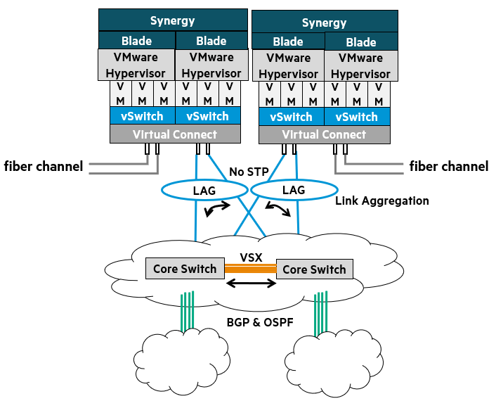
1-tier designis a unique network architecture found in blade server systems.
In this design, the blade enclosure1Built in Internal blade switchGo ToR2 It acts as a switch.
These blade switches, like other common ToR switches, Direct connection to the core networkIt will work.
Advantages of a 1-tier design
- Layer 2 Flexibility: Virtual machines (VMs) can be moved freely, without needing to change IP addresses.
- Reduced management complexity: Simplified network management with fewer devices (switches) to manage
- STP/RSTP not required: VSX3 and LACP4When combined with , a loop-free network can be formed.
- Optimizing VLAN Management: Ideal for VM management, network expansion between sister data centers, and VM mobility.
- Centralized security: IP-based IPS5Centrally manage security by placing devices in the core layer
This type of network deployment is currently The pinnacle of network virtualizationIt shows.
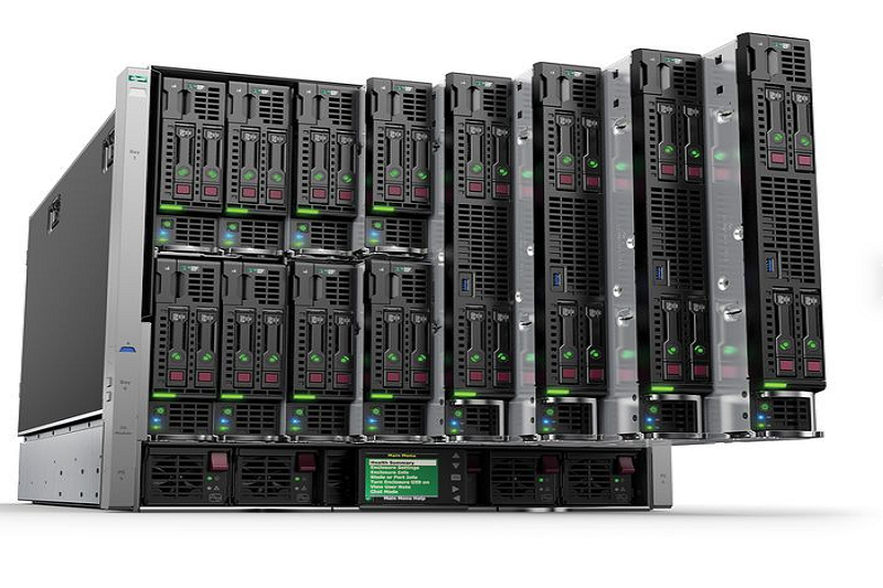
Blade servers offer tremendous compute density per rack, per row, per data center.
HPE has optimized its blade system server portfolio to support the vision and reality of virtualization.
This network design optimizes the realities of high-performance networking with simplicity.
This provides flexibility in VM networking and converged I/O options.
This approach is at the forefront of network design for virtualization, as it leverages both VSX and Virtual Connect.
It works well while enabling seamless management and troubleshooting of VMs.
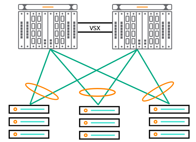
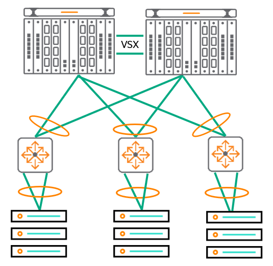
The topology in the figure above reflects a structure where two CX 8400 switches are at the top and are connected to three servers.
It is a one-tier design consisting of a single layer of switches connected to the servers, mainly Most commonly used in small data centersIt will work.
The network edge physically originates from the Virtual Connect, but in reality originates from within the VM and the configured virtual switch.
VMs and virtual switches support VLANs and interoperate with the VSX fabric to enable seamless VM movement via vMotion and high-performance frame forwarding.
LAG in this design6When combining VSX with link failure High-speed link aggregation with re-convergence times of less than 50ms. Additionally, converged network adapters allow you to aggregate and leverage links across all switches to deliver traffic at higher bandwidths.
Blade servers concentrate a lot of computing power in a small space (10 RU), allowing businesses to save space and, in some cases, power and cooling costs. They can also simplify networks. Instead of racks full of servers and complex network topologies, you can achieve the same or better performance with fewer devices and a simpler topology.
For example, the two blade servers in this image can host up to 32 individual servers. Imagine 32 physical servers.
This means 64 power cords (redundant), 64 network connections (redundant), and 64 Fibre Channel connections.
All these cables and connections need to be managed, and because you need more Ethernet ports, you need more switches.
In this topology, all traffic can be handled with only about four 100Gbps connections between the blade servers and the network.
Key Features of Blade Server 1-Tier Design
- The edge physically originates from the Virtual Connect fabric, but actually originates within the VMs and virtual switches.
- Blade servers offer significant compute density per rack, per row, per data center.
- Optimizes high-performance networking.
- Provides flexible VM networking and converged I/O options.
Simplified two-tier design
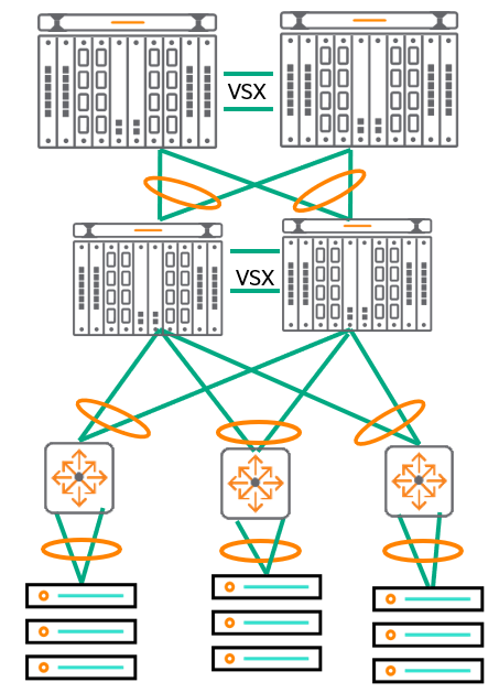
Simplified 2-tier designis very similar to the 1-tier blade design described earlier.
The main difference is that instead of using blade servers, the 1-tier blade design uses Use traditional rack servers and connect them to top-of-rack switches.The point is that it does.
This solution is especially Environments that require a mix of rack servers and blade serversis best suited for.
Than the existing three-tier legacy model Flatter structure, which has the advantage of reducing network latency.
Goals and Benefits of a Two-Tier Design
Layer 2 Flexibility:
Provides the flexibility to move virtual machines (VMs) without needing to change their IP addresses.
Supports long-range vMotion, allowing you to easily migrate VMs even between physically separated data centers.
Reduced management complexity:
Flatten your network architecture using large aggregation switches.
Network management is simplified by reducing the number of devices (switches) to manage.
Reduced spanning tree dependency:
HPE is committed to network optimization and simplification. VSX We recommend using it.
VSX provides a loop-free environment, reducing dependence on the Spanning Tree protocol.
VLAN Management:
Provides a framework for extending VM mobility across data centers, enabling VMs to connect to the network regardless of their physical location.
Centralized security:
Layer 2 networks can centralize security management by allowing IP-based intrusion prevention system (IPS) devices to be placed at the core layer where VLANs are aggregated.
A streamlined two-tier design is an effective network architecture that meets the demands of modern data centers in terms of flexibility, manageability, and improved performance.
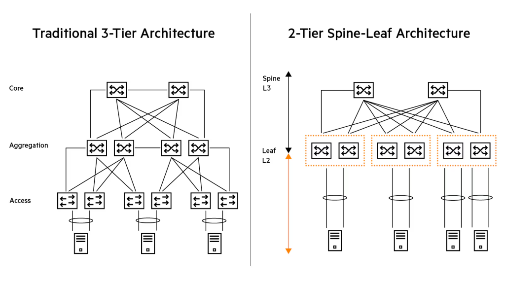
Three-Tier Design: Traditional Hierarchical Data Center Networks
3-tier designis the most traditional and widely used architecture in data center networks.
This design Add an 'Aggregation Layer' between the Access Layer and the Core Layer.do.
In this architecture, many Top-of-Rack (ToR) switches are connected to a small number of aggregation layer switches.
And these aggregation layer switches are again connected to the redundant core switches. dual homed It is connected in this way.
(i.e. each aggregation switch is connected to two core switches to provide redundancy.)
Modern data centers have port capacities such as 10GbE, 25GbE, and 40GbE. Additional bandwidthRequires.
The 3-tier design aligns well with the streamlined management suite and helps ensure interoperability with existing end-of-row (EoR) and top-of-rack (ToR) switches.
Goals and Benefits of a 3-Tier Design
- Layer 2 Flexibility: Provides flexibility to move virtual machines (VMs) without needing to change IP addresses
- Optimized management complexity: Simplify your network and optimize management complexity by using VSX at various layers.
- Reduced spanning tree dependency: We recommend using VSX and LAG for network optimization and simplification.
- VLAN Management: Enables VM mobility by supporting network extension between sites.
Although the presented design focuses on the AOS-CX switch, The VSX feature allows third-party switches to be added at any level and interoperate using standards-based networking. This means you have the flexibility to leverage existing equipment or avoid vendor lock-in.
The Evolution of Data Center Network Architecture: From STP to L3 Fabric
Data center network architecture has been continuously evolving over the past several years.
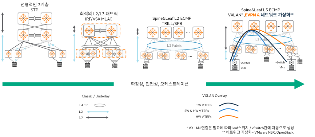
1. Traditional Three-Layer
In the past, we used a traditional three-layer (access-aggregation-core) architecture.
At this time, STP controls the topology, prevents loops, and automatically recovers the network in case of link or switch failure.7We had to use data center protocols like .
But this method Occurrence of unused links, slow convergence (recovery time), lack of multi-pathing support, and limited scalability Network designers are quickly turning away from it due to these issues.
2. Optimized Two-Layer
As an optional alternative to the traditional three-tier system Optimized two-layer Architecture emerged.
This approach stacks protocols such as HPE Aruba Networking VSX and MLAG8By distributing Better link utilization and load sharing through active-active links.It enables.
But even in an optimized tier 2, to meet the high bandwidth demands of large core switches in data centers, Still need protocols like STPHowever, uplinks still pose upgrade and scalability constraints.
3. Spine and Leaf Topology
Spine-leaf topology는 TRILL9 and SPBM10Protocols such asUse it to troubleshoot data center network issues.
- Spine-leaf is Large-scale L2 fabric, allowing VMs to be moved across the DCN without infrastructure changes.
- Transmitting L2 packets over L3 underlaydo ECMP11 load balancingImprove uplink utilization by providing
- but Disability isolation is not possible, limitations of the overlay control plane (flood and learn)12There is this, Multi-site support is not available
4. L3 Fabrics (Layer 3 Fabrics)
Recently, it has evolved once more from the spine-leaf architecture. VXLAN, EVPN, and MP-BGPUtilizing L3 fabricThis has appeared.
- merit: VM mobility, large-scale DCN support, Fault Containment, in L2 and L3 Multi-tenancy (VPN) support
- disadvantage: Limitations such as reduced fabric visibility and increased troubleshooting complexity
Benefits and Scalability of Network Fabrics
network fabricconnects thousands of servers and provides high bandwidth and stable connections. Enables creation of large-scale networksLet's do it.
- If you want to expand your network fabric (spine-leaf), you can do so as much as your spine switches support (taking into account the number of switch ports). Add a leaf switchAll you have to do is do it.
- If you need more bandwidth Add more spine switches and uplinksYou can do it.
- All leaf switches and spine switches are connected with routed interfaces of the same speed, ECMP distributes the load evenly across all available uplinksI'll order it.
This topology The biggest advantageis low latency.
Each leaf switch Reach another leaf switch in one hop at mostBecause you can.
This is very beneficial for east-west traffic within the data center.
Spine-and-Leaf Design: The Core of Modern Data Center Networks
spine-leaf designis one of the most advanced topologies in modern data center networks (DCN).
This design is based on a routing underlay, which is typically OSPF or iBGPConnect the access (leaf) layer and the core (spine) layer using . On top of that, VXLAN encapsulation overlayTransmits L2 packets through L3 networks.
Differences from traditional L2 design
This design has the following major differences compared to traditional L2 designs:
- Using routed links: Instead of L2 link between leaf and spine Routed (L3) linkUse
- ECMP Load Sharing: ECMP is used for traffic distribution purposes.
- Redundancy via routing protocols: Redundancy by leveraging multiple connection and routing protocols
- Loop-Free: No broadcast domain between spine and leaf
Core Principles and Benefits of Spine-Leaf
- Every leaf is connected to every spine switch
- No direct connection between spine switches
- Easy bandwidth expansion: Simply add spine switches to expand available bandwidth.
- low latency
Service Distribution: Leaf Type
In a spine-leaf topology, four types of leaves are typically used to distribute services across leaf switches:.
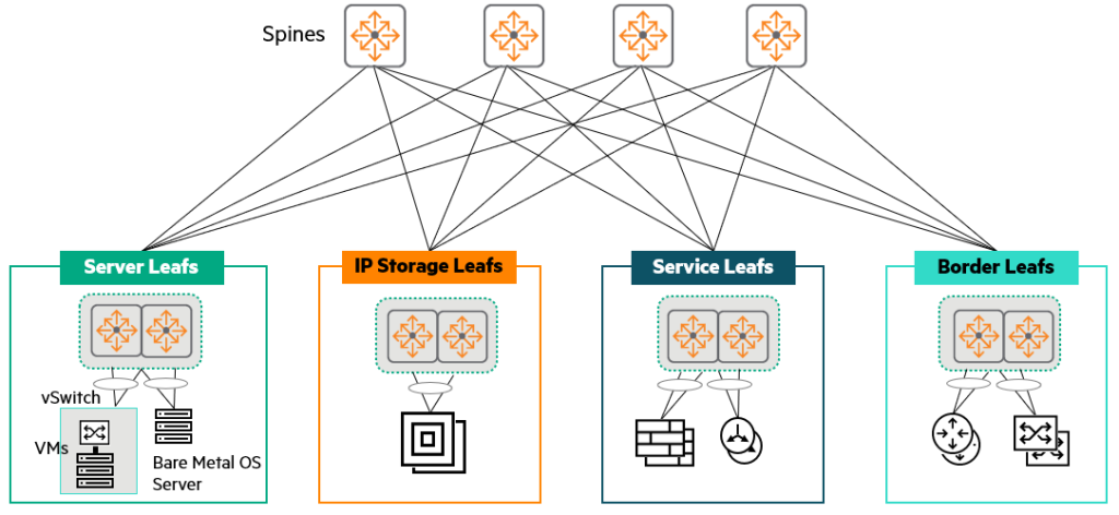
- Server leafs: Leaf servers, including physical servers (bare metal) and virtualized servers, to which servers are directly connected.
- IP Storage leafs: When servers and IP storage are in the same rack, a pair of data center network-optimized switches per rack provides leaf functionality.
- Service leafs: Dedicated leaf hosting network services such as load balancers, firewalls, and IPS.
- Border leafs: A leaf switch that connects one fabric to another, such as a corporate LAN or WAN.
Depending on the scale and fault zone design within the centralized network service and DCN, the border leaf can also act as a service leaf.
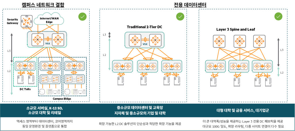
Validity of existing topology
While spine-leaf is the most advanced and recommended topology, this doesn't mean traditional one-tier, two-tier, or three-tier topologies are obsolete. Many customers still operate and deploy these topologies for various reasons.
- Small and Medium Enterprises: 1-tier topology, where the core layer connects directly to servers, blade servers, and storage. This provides simplicity, low latency, and reliability for businesses.
- Medium to large sized companies: If you need to maintain backward compatibility with legacy infrastructure and protocols, 2-tier and 3-tier topologiesis still frequently used.
Summary of key features of each design
Spine-Leaf Data Center:
- Because it uses Layer 3 between racks/leaves No STP required.
- ECMP routingThis load shares the traffic between the leaves.
- Modular/Fixed Port Spine Switches is available, which determines the expansion size of the fabric.
- From leaf to server Link aggregationThis provides traffic load sharing and link/switch redundancy.
Tier 1 data center:
- Modular/Fixed Port Core Switch is available, which determines the number of servers you can connect to.
- From core to server Link aggregationThis provides traffic load sharing and link/switch redundancy.
2-tier data center:
- Modular/Fixed Port Core Switch is available, which determines the number of access switches available.
- Access/Core Link aggregationThis provides traffic load sharing and link/switch redundancy. Loop-free topologyIt is made up of.
- STP is enabled as a backup mechanism to prevent loops.
- From the access switch to the server Link aggregationThis provides traffic load sharing and link/switch redundancy.
How to Design Your Customer's Data Center Network
There are two starting points when designing your data center network.
- Presenting products and innovative features: First, we introduce our latest products and innovative features to customers and show them how these technologies can solve their problems.
- Identifying Questions and Needs: This method involves identifying key requirements by asking questions about the customer's current situation and needs, and then proposing a customized design based on these.
In most cases, to find out the true needs of the customer, I recommend starting with the second approach (asking questions and identifying requirements).
1. Questions to identify key issues/problems
First, it is important to identify the root causes of the major problems or requests that your customers are currently experiencing or anticipating.
What is the main motivation behind this request?
- Are you nearing the end of support for your current equipment and need to migrate to a new data center network?
- Are you currently experiencing a lot of complaints about your manufacturer (lack of support, bugs, etc.)?
- Scalability, port density, and bandwidth issuesHave you encountered this?
- Remodel your data center with a new Point of Delivery (POD) or a few new racks. expansionShould I do it?
- With a new data center network MigrationDo I have to? Is there a migration deadline?
2. Requirements already provided by the customer
Alternatively, the client may have already presented their requirements through an RFP or other means. This is crucial in determining the direction of the design.
- In the data center I want to get rid of STP (Spanning Tree Protocol).
- The network Integration with VMware NSXIt should be.
- On the server Migrate without reassigning IP addressesMust do.
- You should be able to vMotion VMs across multiple data centers.
(How many data centers? What is the WAN infrastructure like?) - On-premise data centers within the next three years 20% extensionI expect it to happen.
(We want to scale through server hardware capacity, VMs, and a transition to containers rather than physical expansion.) - Data centers must have an uptime of 99.9991 TP3T (allowing a maximum of 5 minutes and 15.6 seconds of downtime per year).
- There was an experience where the existing IRF core switch went down due to a bug. How can we avoid this situation in the future?
3. Questions about the currently operating data center
Understanding your existing infrastructure is a critical foundation for new designs.
- today Network topologyWhat is it? (e.g. 3-tier, 2-tier, spine-leaf, etc.)
- Current equipment Provides configuration outputCan you do it for me?
- today How many VMsAnd, How many physical servers?Is it?
- Most servers Connecting to a redundant ToR switch using LACPIs it done?
4. Questions about new data center requirements
We delve into the specific technical requirements for your new data center.
- Do I need to use both IPv4 and IPv6 now? Or are you currently using only IPv4 and planning to use IPv6 in the future?
- Do you utilize multicast routing? (e.g. PIM-SM, PIM-SSM, etc.)
- What routing protocol are you currently using?
- Do you need L2 connectivity between racks?
- Can applications leverage L3 connectivity between racks?
(i.e. is the application designed to cross L3 boundaries?) - What do applications within a data center require from the network?
(e.g. specific bandwidth, latency, specific quality of service, etc.) - What about storage networking?
(e.g., what technologies do you use or plan to use, such as iSCSI, FC, FCoE, RoCE, etc.) - What speed do you need for your new data center?
Do I need 40G or 100G links for my inter-switch connections?
Does your connection to the server require 1G, 10G, or 25G? - What type of connection do you need?
Do you use a Direct Attach Cable (DAC) between switches or fiber?
What cable do you use to connect to the server: UTP, DAC or fiber? - What kind of scalability do you need? IPv4 (IPv6) routing/MAC/ARP table size
- How many total server ports do you currently need?
- Server MLAG on dual ToR switch13Is it going to be connected?
- How many spare pots do you need for growth?
- What is the target oversubscription ratio on the ToR switch?
- What are the essential software features? Is VXLAN/EVPN required?
These numerous questions should help you gain a deep understanding of your customer's current situation and future goals.
Based on this, we can design the optimal data center network architecture and solution.
Data Center POD: A Modular Approach to Reliability and Efficiency
If your customers' biggest concerns and needs are Network uptime of the application, Minimize the impact (scope of failure) of network problems, and Ability to quickly diagnose and resolve network problemsIf so, the most recommended solution is POD (Point of Delivery)14 Base architectureno see.
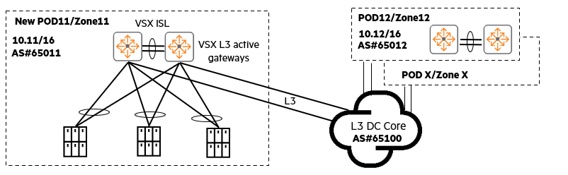
Some organizations operate multiple data centers, often POD Or, as they are called, Availability Zones. A POD-based architecture has the following characteristics:
- Optimal placement of the same application: Applications that require similar and fastest East-West network connectivity Placed inside the same PODMust do.
- Separate PODs by application: Different applications are Placed on different PODsYou can do it.
- North-South traffic flow: North-South traffic from end users L3 data center corePasses through.
- L2 isolation within the POD: Each POD is Your own L3 subnet. L2 (Layer 2) connectivity is restricted to within the POD only, preventing L2 network problems or broadcast traffic from propagating externally.
- Flexible POD sizes: One POD is A full row of one rack, two racks, or even ten racksIt may also encompass .
Advantages of POD-based architecture
- Maximum network availability and uptime: Even if a network problem occurs on one POD, It does not affect other PODs The stability of the entire system is increased.
- Independent upgrades: Each POD Upgrade independentlyThis can reduce the risk of service outages and provide flexibility in maintenance.
- Flexible POD configuration: PODs are very flexible. For example, you can use them as a 1-tier, 2-tier access core, 2-tier leaf/spine, or use VXLAN within the POD. Different types of PODsYou can utilize it.
A POD-based architecture is a highly effective strategy for managing data center complexity, minimizing the impact of failures, and maximizing overall service reliability.
Server Connection Methods: Essential Considerations for Building a Stable Data Center
When designing a data center, deciding how to connect servers (or endpoints) to the network is a simple but crucial step.
Choosing a server connection method depends on the data center network. Availability, Resiliency, and PerformanceBecause it has a direct impact on.
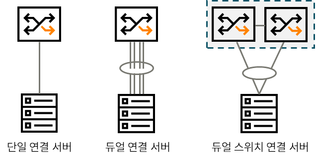
1. Single Attached Server
This method connects the server to the switch using one network card (NIC) and one cable.
- merit: Save on switch ports and cables.
- disadvantage: Lack of redundancy and resilienceIf that NIC, cable, or switch port fails, the server is completely disconnected from the network.
2. Dual Attached Server
Using two or more NICs and cables on the server Connect to one switchThis is how it is done.
- merit: About NIC and cable Link redundancy. In addition, it uses technologies such as Link Aggregation. Increase bandwidthYou can do it.
- disadvantage: connected If the switch itself fails, the entire server becomes unavailable on the network.
3. Dual-Switch Attached Server – HPE Recommended Practice
Connect two or more server NICs to different switchesThis is how HPE recommends doing it.
This approach offers the following advantages:.
- Link, NIC, and Switch RedundancyIt provides all of them.
Even if one switch fails, service continuity can be maintained through the other switch. - When combined with link aggregation More bandwidth to the servercan improve performance by providing .
In this post, we looked at the architecture you need to know to design a data center network.
As IT technology advances, data processing methods and computer environments have also changed. Naturally, networks have also evolved accordingly.
The technologies and knowledge accumulated over many years are also changing the environment and design of data centers.
To understand trends, you must also be familiar with previous designs and their pros and cons.
This is because the latest technology is not always the right answer, nor does it necessarily have to be adopted.
- The physical container that houses the servers ↩︎
- Top of Rack ↩︎
- Virtual Switching eXtension ↩︎
- Link Aggregation Control Protocol ↩︎
- Intrusion Prevention System ↩︎
- Link Aggregation Group ↩︎
- Spanning Tree Protocol ↩︎
- Multi-Chassis Link Aggregation ↩︎
- Transparent Interconnection of Lots of Links ↩︎
- Shortest Path Bridging for Media ↩︎
- Equal-Cost MultiPath ↩︎
- As the number of hosts in a broadcast domain increases, the negative impact of flooding packets increases. ↩︎
- Multi-chassis Link Aggregation Group ↩︎
- Modular architecture where multiple server racks, network equipment, storage, etc. come together to form a single independent service unit. ↩︎