The Spine-Leaf architecture acts as a core Spine switch, the access layer Leaf switch, and numerous other data centers that handle compute and storage resources. endpointIt consists of . This architecture is highly scalable, efficient, and optimized for low-latency communication, making it ideal for modern data center environments that require high-performance networks.
Goals of a typical data center architecture
There are several distinct advantages that make Spine-Leaf architecture a popular choice:
- High Scalability: Modularly add leaf switches and endpoints as needed without network disruption, optimizing cost and resource utilization.
- Low Latency: Minimizes data transfer latency through direct, non-blocking connections between leaves and spines.
- High Bandwidth: Effectively prevents traffic congestion through multiple high-speed links connecting each leaf switch to the spine.
- Redundancy and Resiliency: Redundancy is designed into all layers (switches, paths) to minimize service interruption even in the event of a specific hardware failure.
- Simplified network design: Designed with a predictable two-tier architecture, it is easy to manage, troubleshoot, and enforce security policies.
- Enhanced Security Segmentation: Effectively logically isolate your network to prevent unauthorized access to sensitive data.
- Virtualization support: Responds quickly to dynamic changes in virtual machines (VMs) and containers and allocates resources efficiently.
- Hybrid and multi-cloud support: Supports borderless expansion between your own data center and cloud resources.
Key Components
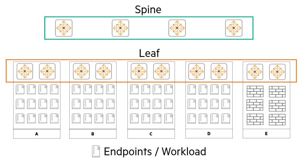
The core components of the Spine-Leaf architecture are: Spine switch, leaf switch, endpoint There are three.
① Spine Switches
- role: It serves as the "core" of the spine-leaf architecture and is responsible for interconnecting all leaf switches.
- characteristic: It is typically composed of high-speed, high-capacity switches and must ensure low latency for fast communication between leaf switches.
- importance: For reliability, a redundant configuration (at least two) is strongly recommended. The spine switch routes traffic between leaf switches and ultimately forwards traffic to the outside world, such as the Internet or other data centers.
② Leaf Switches
- role: It connects directly to endpoints within the data center, acting as the network's "access layer.".
- characteristic: It features high port density to accommodate numerous endpoints. It supports L2/L3 networking functions and provides low-latency connectivity to endpoints.
- metaphor: If the spine switch is a 'highway interchange', the leaf switch can be understood as the 'regular road' in our neighborhood.
③ Endpoints (Endpoints / Workload)
- role: It refers to all devices residing within a data center, such as servers, virtual machines, and storage devices, and is also called 'workload'.
- type: These include application servers, database servers, load balancers, storage arrays, and more, and can be either physical or virtualized servers.
- function: Spine and leaf switches use the network infrastructure provided by the switches to communicate with each other, access external resources, and provide services to users and other applications.
Traditional vs. Spine-Leaf Architecture Comparison
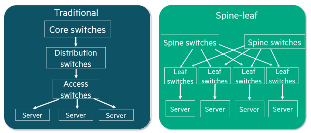
Comparing traditional data center network designs to modern spine-leaf architectures is crucial to clearly understanding the differences between the two architectures and the benefits spine-leaf offers.
| Comparison items | Traditional Network | Spine-Leaf |
| Design structure | Layer 3 (Core – Distribution – Access) The structure is complex because there are many layers. | 2nd tier (Spine – Leaf) Reduce complexity by simplifying it into two layers. |
| Topology characteristics | Hierarchical topology Traffic flows in a hierarchical order. | Direct Connection Non-blocking connection between leaf and core networks. |
| Communication efficiency | High latency East-West traffic processing requires multiple layers. | High bandwidth and low latency Ensure fast and efficient communication through direct connection. |
| Scalability | Limited scalability Adding equipment risks hierarchical redesign and operational disruption. | High scalability Ability to add leaves/endpoints instantly without affecting the core. |
| traffic route | Complex routing Traffic patterns are difficult to predict because the routes are mixed. | Predictable path Easy to plan and optimize with consistent traffic patterns. |
| Handicap points | There are many potential failure points in the hierarchical structure. | Simple structure makes management and troubleshooting easy. |
💡 Summary: As you can see from the table, the traditional method emphasizes 'vertical hierarchy' and is advantageous for external communication, whereas spine-leaf emphasizes 'horizontal connection (fabric)' and is optimized for communication between massive servers within a data center.
in other words, The traditional structure is the elevator in a high-rise building.It is the same. To go to another floor, you must go up and down through the central elevator hall. On the other hand, Spine-leaf is a single-story building with all rooms directly connected to a hallway.It is a structure that connects you directly to your destination by simply opening the door and going out.
Details and limitations of traditional design
A. Traditional Two-tier Design
It is easy to build and maintain due to its simple structure without a distribution layer, but it has a fatal weakness.
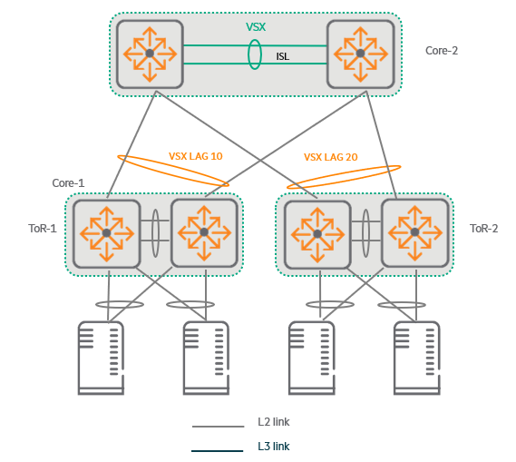
- Bandwidth limitations: The performance of the core switch will soon become full bandwidth.
A VSX stack can only contain a maximum of two switches, so you cannot add more core switches. - Network size limits: You can only scale your network as much as the number of physical interfaces your core switch has.
B. Traditional Three-tier Design
This method allows for connecting more access switches by adding an aggregation layer in the middle.
Depending on where the routing is performed, different limitations may appear.
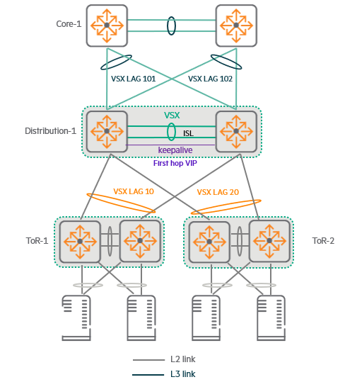
When performing routing (L3) at the middle (Distribution) layer:
- VLAN extension is only possible between access switches connected to the same distribution switch pair (VSX Pair).
- Since each distribution switch creates a large L3 domain, protocols like MSTP are essential to prevent loops.
When performing routing (L3) at the core layer:
- VLANs can be spread across the entire data center, allowing free movement of virtual machines (VMs).
- However, routing performance is still limited to core switch performance.
Since VSX only supports up to 2 units, adding another VSX pair for performance would significantly complicate the configuration and require MSTP Multiple Regions setup. - Enlarged L2 domainThis greatly increases the risk of loops and broadcast storms.
C. Problems with large-scale three-tier designs
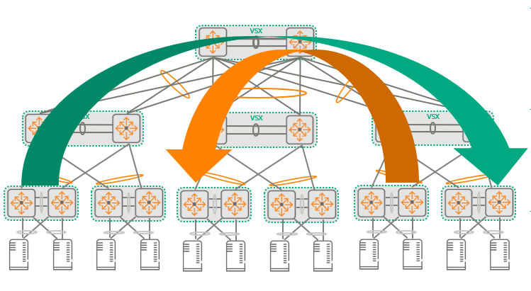
As networks grow and the number of distribution switches increases, east-west traffic (communication between servers) must traverse more links and switches, dramatically increasing latency. Furthermore, managing VLANs across numerous access switches becomes cumbersome and error-prone.
Loop prevention protocols like Spanning Tree only add more failure points for administrators to monitor and troubleshoot.
Spine-Leaf Design
As mentioned earlier, the spine-leaf topology offers many advantages. Let's recap the key points.
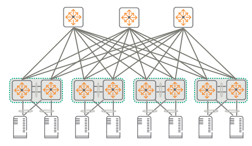
1. Key Advantages (Recap)
- Lower Latency: Any server within a data center only needs to go through three hops (Leaf > Spine > Leaf) to communicate with any other server, enabling extremely fast, low-latency communication.
- Bandwidth scalability: If you need more bandwidth, simply add a new spine switch.
For example, in an environment with two spines, adding one more spine to create three spines immediately increases the bandwidth by 50%. - Easy expansion: There is no need to take your network down when adding new spine or leaf switches.
Additionally, since it is configured based on L3 connectivity (routing), there is no need to worry about spanning tree loops or broadcast storms.
2. Technical Limitations
But even the seemingly perfect Spine-Leaf has limitations that must be considered during design.
- Limit on the number of leaf switches: The total number of leaf switches (or racks) that can be installed in a data center is Number of interfaces the spine switch hasis determined by.
Example: If a Spine switch has only 48 ports, then only up to 48 Leaf switches can be connected.
Adding a new Spine does not mean that you can connect more Leaves.(Because every Leaf must be connected to every Spine)
- Uplink port requirements for Leaf switches: As you increase the number of spine switches to increase bandwidth, you will also need more physical ports on the leaf switches to connect to the spine.
Advanced Architectures
Super Spine
In large data centers, multiple equipment rooms must be consolidated into a single physical resource pool.
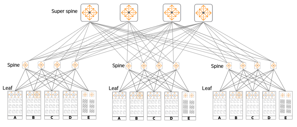
What is used at this time Super Spine It's architecture.
It is primarily used in hyperscale enterprises or campus-type data centers, handling massive east-west traffic between different data halls.
- Spine: Aggregates traffic within each equipment room.
- Super Spine: Interconnects spines in multiple equipment rooms to support unified communications throughout the data center.
Sub-leaf
Many data centers still use copper connections, and sub-leaves can be utilized for this.
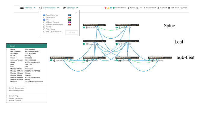
Sub-leaves are connected to leaf switches, not spines.
- merit: For leaf switches that only support 10G or more Older servers with 1G NICsIt allows you to connect them.
- characteristic: The sub-leaf acts as a simple L2 switch that does not participate in EVPN VXLAN complexities. This role is typically performed by the Aruba CX 6300M model, either standalone or in a VSF stack.
Distributed Services Architecture
The traditional approach was to send all traffic to a central security device (such as a firewall) for inspection.
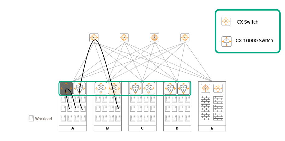
but Distributed Service Architecturedistributes security policies to the location closest to the application (server).
- Core Equipment: Aruba CX 10000 Deploy the switch as a Top of Rack (ToR) leaf switch.
- How it works: Traffic generated by a workload (server) is immediately forwarded to the security engine embedded in the ToR switch for inspection. After inspection, it is forwarded to other workloads within the same server or to other servers.
- Comparing Existing Distributed Service Architectures with Traditional Security Architectures
| division | Centralized Security (Legacy) | Distributed Service Security (CX 10000) | Note (Advantage) |
| traffic flow | Hairpining Send all data to a central firewall | Shortest Distance (Direct) Immediate inspection at the server connection switch (ToR) | Reduced latency |
| Core load | Overload occurs Traffic for security checks occupies the backbone network. | Zero load Protect your core by processing traffic locally | Maximize bandwidth efficiency |
| Security scope | Perimeter Security Focus Mainly defending against external incoming traffic (NS) | All-round security Microsegmentation up to server-to-server (EW) traffic | Zero Trust |
| Scalability | Passive/Limited Expensive equipment additions are required when expanding equipment. | Automatic/Linear Security capacity also increases when racks are added. | Reduce expansion costs |
| Management system | Silo Network and security teams manage separately | Unified Unified network/security control on a single platform | Increase operational efficiency |
💡 Key Takeaway
- Eliminate hairpining: The name "hairpin" comes from the way traffic passes through the central firewall and then returns, resembling a hairpin (U-shape). Distributed services eliminate this "U-turn" section, thereby relieving congestion on the network highway.
- Solving Appliance Sprawl: As the network grows, the problem of dedicated equipment such as firewalls and load balancers increasing exponentially is absorbed by the DPU (data processing unit) inside the switch, simplifying the infrastructure.
- Democratization of security: It achieves ‘security built-in’, where security is not only provided at specific points, but all switch ports become security boundaries.
Key Use Cases of the Spine-Leaf Architecture
Spine-leaf is used across a wide range of industries to meet the needs of modern data center networks:.
- Large Enterprises: Ideal for large organizations with extensive and complex data center requirements, such as multinational corporations or financial institutions.
- High Performance Computing (HPC): Between operation nodes low-latency communicationThis core is ideal for HPC clusters, delivering significant performance for scientific research, simulations, and complex data analysis tasks.
- Internet Service Providers (ISPs): ISPs requiring robust and scalable networks can optimize traffic flow and ensure reliable connectivity through spine-leaf.
- E-commerce and Retail: It's essential for online retailers who need a responsive, scalable network to manage website traffic, manage inventory, and process customer transactions.
- Content Delivery Networks (CDNs): It is used to quickly and efficiently distribute video or web page content to users around the world.
- Healthcare: It is used in healthcare organizations that require reliable, low-latency networks for electronic health record (EHR) systems, medical image transmission, telemedicine, and data sharing between medical professionals.
- Gaming: It is suitable for the server infrastructure of online gaming companies where real-time interaction and fast response speed are essential.
- Data Analytics and Big Data: It is introduced to address performance bottlenecks in industries that rely on data analysis, machine learning, and big data processing, such as finance and marketing.
- Education: It is used by educational institutions that use e-learning platforms, online lectures, and digital resources to stably accommodate a large number of concurrent users.
Maximum Spine Switch Capacity by Leaf Model
When designing a network, the number of spine switches that a leaf switch can support depends on the port configuration of the model.
Especially when redundant leafs (Redundant ToR) are used for availability, additional inter-switch connection ports are required, reducing the number of acceptable spines.
| Leaf Switch Model | When configuring a single ToR Maximum number of spines | When configuring redundant ToR Maximum number of spines |
| CX 9300-32D | 16 (Based on 400 Gbps) | 15 (Based on 400 Gbps) |
| CX 8325-48Y8C | 8 | 6 |
| CX 10000-48Y6C | 6 | 4 |
| CX 8360-48Y6C v2 | 6 | 4 |
| CX 8360-32Y4C v2 | 4 | 2 |
| CX 8360-48XT4C v2 | 4 | 2 |
💡 Design Tip: Why are the number of ports limited?
- Uplink port limitations: The fundamental principle of spine-leaf is that "every leaf must be connected to every spine." Therefore, if a leaf switch has only four high-speed uplink ports, you can only install up to four spine switches.
- Port consumption during duplication: When you redundantly connect two leaf switches, such as a VSX, ports are used to connect the two switches to each other. This reduces the number of free ports available for connecting to the spine compared to a single configuration.
- Bandwidth Plan (Oversubscription): Beyond simply matching the number of ports, you need to calculate the ratio of data flowing from servers (inbound) to data flowing out to the spine (outbound). If you need more bandwidth, you should choose a leaf model with a higher uplink capacity (e.g., 100G to 400G).
Technical Considerations When Choosing a Spine Switch
When selecting a spine switch, you should comprehensively consider not only current connectivity but also future scalability and routing processing capabilities.
1. Physical specifications and expandability
- Interface Speed: Determines the connection speed (100G, 400G, etc.) to the leaf switch.
- Number of Interfaces and Growth: You need to ensure that you can accommodate the number of leaf switches you need now, and that you have enough spare ports when you add more leaf switches in the future.
- Interface Types: Consider the port type to suit your distance, whether you will use optical cables (Optics) or direct-to-analog converters (DACs).
2. Core Protocols and Overlays
- MP-BGP and EVPN address families: Enables L2 communication (VLAN extension) between racks in modern data centers. EVPN overlay To use the technology, a spine switch is required. MP-BGP EVPNThis is a very critical selection criterion.
- Routing protocol support: Check whether various routing protocols such as OSPF and BGP are supported for underlay configuration.
3. Routing table size and efficiency
- Forwarding Table Optimization: An interesting phenomenon occurs when using EVPN overlay technology. The actual data transmission takes place over a virtual tunnel, so physical devices communicate with each other. The underlay L3 forwarding table is kept surprisingly small.It can be.
reason: Set on all switches in spine-leaf structure Loopback addressBecause you only need to pass the data.
- Importance of table size: Nonetheless, to efficiently manage routes throughout the data center, the overall routing table size that the switch can handle must be sufficient to avoid performance degradation.
💡 “Underlay and Overlay”
- Underlay: Actually existing physical highwayno see.
It is the physical infrastructure that allows switches to find their way to each other via loopback addresses.- Overlay: Built on that highway Virtual private tunnelno see.
This tunnel (EVPN VXLAN, etc.) allows servers in different racks to communicate with each other at L2 as if they were on the same floor.spine switchIts role is to maintain the integrity of this highway (underlay) and to accurately relay information (EVPN) about the numerous virtual tunnels passing over it.
Deployment Scenarios
Depending on the size of your data center and the distance between switches, you need to choose the appropriate cables and transceivers.
1. Connecting the CX 8325 (Spine) and CX 10000 (Leaf)
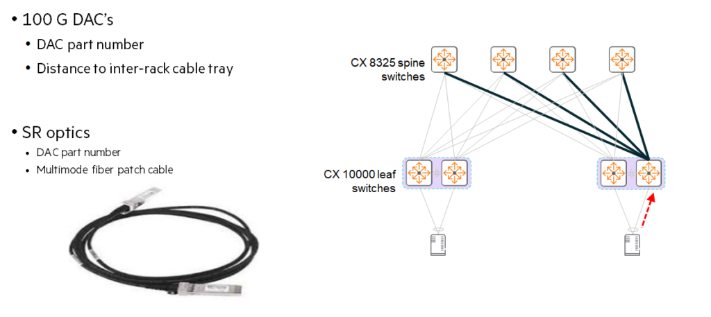
This combination is often used in typical high-performance data centers.
- DAC (Direct Attach Copper) Cable: Use when the distance between switches is very short (in the same rack or right next to each other).
Low cost and low power consumption small data centersIt is the most economical. - AOC (Active Optical Cable): It is lighter and more flexible than a DAC, and is suitable for connecting slightly longer distances.
- Optics & Fiber (Optical Cable): If the data center is large and the distance between switches is long, optical transceivers and optical cables must be used for connection.
2. Connecting CX 9300 (Spine) and CX 10000 (Leaf) (Breakout Technology)
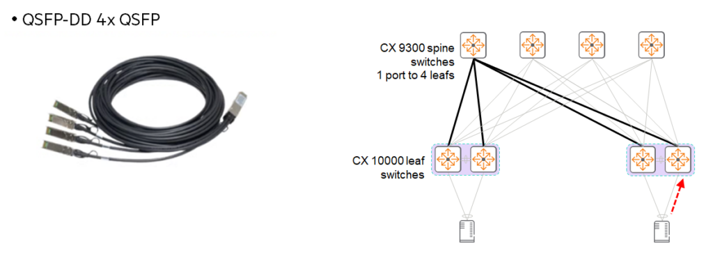
CX 9300It is an ultra-high bandwidth switch with 32 400G Ethernet ports.
To efficiently connect this to the leaf switch, Breakout Use technology.
- 400G QDD to 4x100G QSFP28: Plug a 'split cable' into one 400G port 4 x 100G connectionscan be divided into.
This means that one port on the spine can supply 100G of bandwidth to each of the four leaf switches. - advantage: Maximize port utilization and simplify wiring on your spine switches.
3. Connection between CX 9300 (Super Spine, etc.)
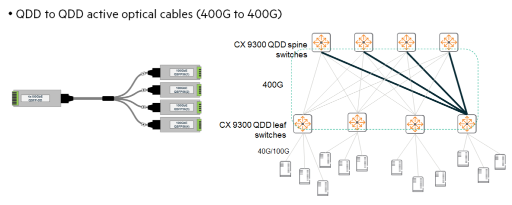
If you connect spines and spines (or super spines), you can do it without splitting them. Straight 400G linkYou can use it as is to secure overwhelming backbone bandwidth. If necessary, you can distribute it further across multiple 100G connections to the leaf tier.
💡 Cable Selection Guide
- DAC (copper wire): “Our switches are right next to each other.” -> Cheap and sturdy.
- AOC (Application of Optical Color): “The distance is a bit far and the cable shouldn’t be too heavy.” -> Flexible and lightweight.
- Optical cables (Optics): “I need to connect it to a switch in another room.” -> Long distance transmission possible.
In this lecture, we will learn about the heart of the modern data center. Spine-leaf architectureWe took an in-depth look at the design philosophy.
If the networks of the past were simply hierarchical structures connecting devices, now ‘Scalable, fast, and secure.’ We've evolved into an intelligent fabric. Always remember that the choice of a single switch port or cable determines the future scalability and performance of your entire data center.