Virtual Routing and Forwarding (VRF) is used to build a virtual private network (VPN). L3 (network layer) isolation technologyno see.
VRF isolates routing tables from other VPNs in the system and allows the use of duplicate IP addresses.
That is, VRF is Multiple routing table instances can exist simultaneously within a single router.It is a technology that enables you to do so.
Because each routing instance is independent of the others, they will not conflict with each other even if they use the same or overlapping IP addresses.
This improves network functionality by allowing network paths to be segmented without the need for multiple routers.
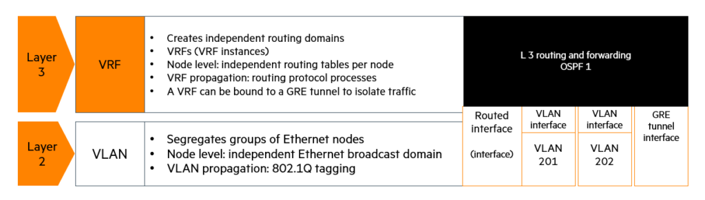
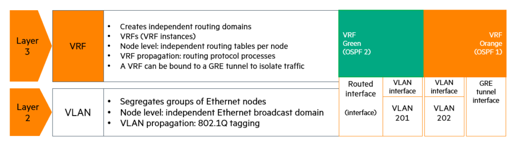
VLAN at Layer 2and VRF are very similar in configuration.
Understanding VLANs makes it easier to understand how VRFs support additional routing table configuration within a single device.
- VLAN: independently isolated Layer 2 (Data Link Layer) Have a network.
- VRF: independently isolated Layer 3 (network layer) Have a network.
Just as each access port in a VLAN belongs to a single VLAN, each Layer 3 routed interface in a VRF belongs to a single VPN instance. Examples of interfaces that can be assigned to a VRF instance include:
- Layer 3 interface of VLAN: Example) Interface VLAN 10
- Routed ports: Example) Gigabit Ethernet 1/0/2
- Loopback interfaces: Example) Interface loopback 1
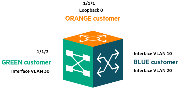
If you look at the picture above, you can see that multiple interfaces are defined in different VRFs.
Interface 1/1/1 and loopback 0 are ORANGE VRF, interface 1/1/3 and VLAN 30 are GREEN VRFAnd VLAN 10 and VLAN 20 interfaces BLUE VRFis set to .
Each VRF configured by the network administrator has a separate interface and a separate routing table.
One thing to remember is that even though each VRF has a separate routing table, the hardware resources of the actual switch (IP routing table space, ARP table, etc.) are shared and used by all VRFs.
Default VRF configuration on AOS-CX switches: When the switch is first powered on (out of the factory), two VRFs are present by default:
- default VRF: This is the space that all L3 interfaces are allocated by default.
- mgmt VRF: This is a management VRF allocated exclusively for equipment management ports.
L2 and L3 network segmentation
Route Leaking allows you to distribute or “leak” route information between multiple VRFs in a controlled manner.
There are two ways to leak a route from one VRF to another:
- Static routes and MP-BGP
- Dynamic route leak using route-targets
VRF Use Cases
Case 1: Multi-tenant Data Center
Access Control Lists (ACLs) can be used to isolate customers (tenants), but ACLs must be configured individually, are complex, and prone to error. Furthermore, because all customers operate within the same routing table, a single incorrect ACL configuration can result in access to other customers' networks. By default, the network allows all communication, and only meticulously crafted ACLs can block it.
the other side VRFSeparates customer resources by creating separate routing tables from the design stage.
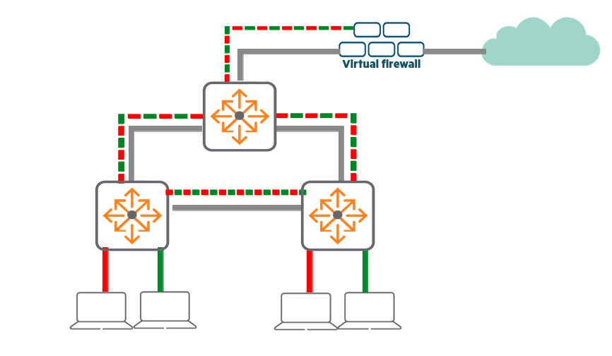
By default, communication between VRFs is not allowed, and traffic is allowed to pass only with explicit additional configuration (route leaks).
Therefore, it is much simpler to set up and maintain than traditional ACLs.
It is typically configured to connect to a public Internet gateway in conjunction with a customer-specific virtual firewall, which must be VRF-aware to maintain separation.
Case 2: Data Center with Independent Business Units (BUs)
This is when a single physical data center is shared by multiple departments, teams, or applications.
Management teams can isolate traffic from each department while using the same equipment.
Another example Test and Development NetworkThere is.
New software can be tested without impacting your production network by validating it in a completely isolated virtual network.
Case 3: Duplicate IP segments
Corporate mergers and other events may result in multiple departments needing to use the same IP address range.
VRFs allow you to isolate networks and address schemes by department without changing IP addresses.
If inter-VRF communication is required, a firewall must be installed at the Layer 3 boundary. NAT Communication can be enabled through functions.
Case 4: Isolated Management Network
This is when a separate network is built for equipment management.
L2 switches do not have IP addresses from the customer network, so by default the management subnet is isolated.
However, L3 devices (devices that perform inter-VLAN routing) are designed so that users can access the IP interfaces of the devices.
So for the management interface Dedicated VRFIt blocks access by general users by creating a firewall that allows management protocols such as SNMP, Telnet, and SSH to operate only within it.
Case 5: Data Center Shared Services
Each customer uses an isolated VRF, but central firewall, backup, monitoring, and security services are available. public servicesThere are times when you need to share.
Customers can continue to use routing protocols like OSPF within their VRFs, while public service instances can use other protocols.
At this time Path leak The technology allows each VRF to remain isolated while allowing only the specific paths it needs to pass through to each other.
VRF configuration steps
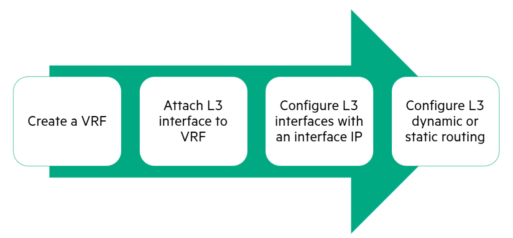
1. Creating a VRF
A VRF is a collection of Layer 3 (L3) interfaces and routing rules. The first configuration step is creating a VRF.
- Create VRF:
vrfCreates a named VRF instance with the command:.
When you create an instance, the command prompt enters the context of that VRF configuration.
switch(config)# vrf Customer_A- Check VRF:
show vrf [vsx-peer]The command displays the status of the specified VRF instance and the interfaces associated with it.vsx-peerThe option shows the output of the VSX peer switch.
(If the switch does not have VSX setup or the ISL is down, the peer's output will not be displayed.)show vrfJust enter the following and it will show you all the VRF information.
switch# show vrf Customer_A
VRF Configuration: ------------------ VRF Name: test Interfaces Status ------------------caution: By default, a new VRF has no interfaces associated with it, Deleting a VRF also deletes all L3 settings associated with that VRF.
2. Attach L3 interfaces to VRF
- Basically all interfaces are
defaultIt is mapped to VRF. - Routed ports, LAGs, VLAN interfaces, and loopback interfaces can be connected to a VRF.
switch(config)# interface 1/1/29
switch(config-if)# vrf attach Customer_A
switch(config)# vlan 3
switch(config-vlan)# exit
switch(config)# interface vlan 3
switch(config-lag-if)# vrf attach Customer_A
All L3 interfaces on the device are enabled by default. default Since we are connected to a VRF, after creating and configuring the VRF, the next step is to associate the desired interfaces with the new VRF.
- Delete Settings Warning: When connecting or disconnecting an interface to a VRF All settings for that interface will be removedIt will work.
At this time, “All Layer 3 con-figurations associated with the VRF will be deleted. Continue (y/n)?“A warning message will appear saying “.- Reset IP address: When defining a VRF with an IP address on the interface, IP address deletedSo, remember to re-enter the IP address for that interface.
3. Configure IP on L3 interfaces
- When you connect an interface to a VRF, the interface settings are deleted.
- After connecting, you must reset your IP address.
switch(config)# interface 1/1/29
switch(config-if)# IP address 10.20.20.1/24
switch# show ip route vrf Customer_A
Displaying ipv4 routes selected for forwarding '[x/y]' denotes [distance/metric] 10.20.20.0/24, 1 (null) next-hops via 10.20.20.1, [0/0], connected 90.0.0.0/24, 1 unicast next-hops via 30.0.0.1, [1/0], static
After setting the IP address, show interface brief The command does not show VRF membership (which VRF it belongs to).
To check this show vrf or show ip route You must use the command.
for example, show ip route vrf Customer_A Through the command Customer_A You can check the IP information set in VRF.
4. Configure routing
- You can use either static or dynamic routing (exactly the same public routing table and configuration options).
- In most commands, additionally
vrfKeywords are required.
Static Routes
To add an IPv4 static route to a VRF, specify the destination IP address, subnet mask, and next hop IP address or interface, then, Finally, specify a VRF namedo.
- Example of configuring static routing within a VRF:
switch(config)# ip route 20.0.0.0/8 10.20.30.44 vrf Customer_AOSPF
Each VRF requires a separate OSPF process.do.
for example, Customer_A You can configure OSPF process 2 for VRF.
When configuring an OSPF process, you must specify a unique process number and the VRF to which this process will be associated.
- Example of OSPF configuration inside a VRF:
switch(config)# router ospf 2 vrf Customer_A
switch(config-ospf-1)# Area 0
Each OSPF process has its own LSDB and requires a unique router ID (router-id) to exist within that VRF.
Before configuring OSPF, you must first configure a loopback address in the VRF.
If there are no routed interfaces available within the VRF, the OSPF process will not start because no router ID can be assigned.
5. Inter-Virtual Router Forwarding: IVRF (Inter-Virtual Router Forwarding)
VRF allows you to partition a physical switch into multiple virtual router instances (VRFs).
Each VRF has isolated control and data planes. This isolation prevents traffic from traversing VRFs, allowing multiple unique routing tables to coexist within a single physical L3 switch/router.
Route Leaking (IVRF) allows routes to be distributed (leaked) to multiple VRFs in a controlled manner. There are two methods:
- Static routes
- Multiprotocol BGP (MP-BGP) (or dynamic route leak using route-targets)
Route leaks enable strictly controlled routing communication between VRFs.
Although the original purpose of VRF is isolation, real-world scenarios may require communication between VRFs.
One of the advantages of using VRF here is that it allows for a limited number of leak paths to be created.
Communication between VRFs is not possible without manually defining routes.
Therefore, it is easier to implement access control than using Access Control Lists (ACLs) within a single routing table.
An example of route leakage is specifying a specific subnet so that VRF B can access VRF A.
For example, VRF B 10.2.2.0/24of VRF A 10.1.1.0/24To reach, For two-way communication Both paths must leak to their respective VRFs.
Another scenario is a backup service or monitoring service within a data center (10.254.0.0/16) is useful when providing customer VRFs.
Additionally, route leaks between the public routing table and the VRF can occur when accessing the Internet through a central firewall.
The firewall can exist in a dedicated VRF (see figure below) or in a public routing table.
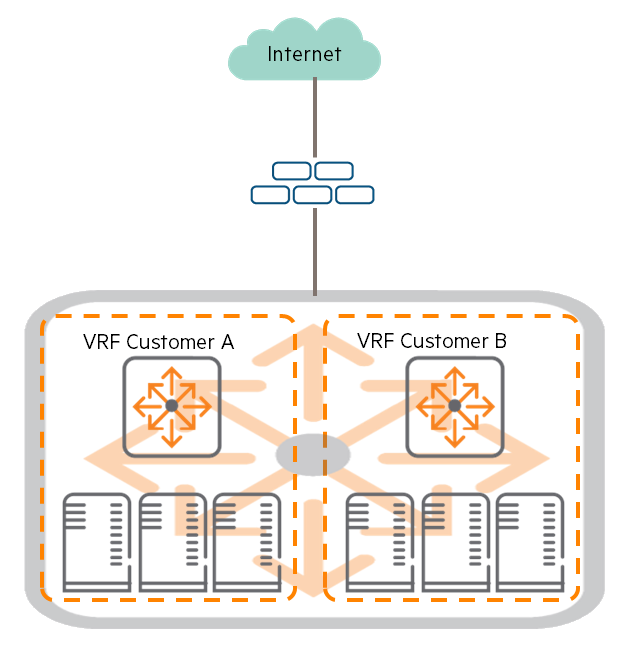
When configuring route leaks, you must leak the required routes to both VRFs to enable bidirectional communication.
⚠️ AOS-CX Restrictions and Limitations:
- The AOS-CX switch is Does not perform NAT (Network Address Translation)
If you only use these devices Duplicate IP addresses cannot be used between VRFs that are trying to communicate. (NAT is only supported on routers) - Supports up to 256 route-targets per VRF when dynamic route leaking occurs.
- Supports up to 16,000 dynamic leak paths per system.
- Multicast path leaking is not supported.
- Route filtering for leaked routes is not possible when using BGP.
- No cascaded leakage: (Example: VRF1 → VRF2 → VRF3 cannot be passed through)
mgmtVRF cannot be used for route leaks.
6. IVRF static route leak
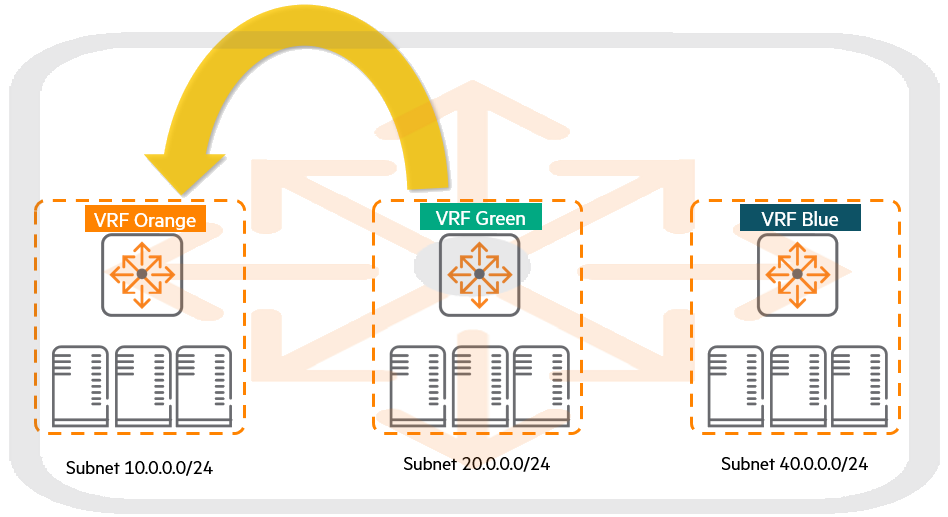
ip route or ipv6 route Here are the steps to leak routes between two VRFs using the command:
- Check route: The route to be exported (leaked) to another VRF Source VRFIt must exist in .
(must be a static, direct connection, or OSPF-learned route) - Command:
ip route vrfyes:
OrangeIn VRF100.0.0.0/24The pathBlueTo leak to VRF:
ip route 100.0.0.0/24 1/1/1 10.0.0.1 vrf Blue
- Multipath (ECMP): Multiple routes can be leaked if they belong to the same source VRF.
Example: If the 100.0.0.0/24 prefix is reachable through two routes in VRF Orange, you can use the following command to leak both routes to VRF Blue:
ip route 100.0.0.0/24 1/1/1 20.0.0.1 vrf Blueip route 100.0.0.0/24 1/1/1 20.0.0.2 vrf Blue
- No duplicate IPs: same
100.0.0.0/24The pathOrangeVRF andGreenIf you learn from both sides of the VRF, you can do both simultaneously.BlueLeaking to VRF is not allowed.
IVRF example
This example has an AOS-CX switch running three VRFs: Orange, Green, and Blue.
Depending on your customer requirements, you may need to configure some routes to be shared (leaked) between VRFs.
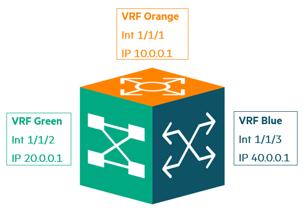
To do this, a VRF must first have an active route to that destination, and once the route is established, it begins sharing that route with other VRFs.
There is a slight difference between sharing external paths and sharing directly connected paths.
When sharing external routes, you must explicitly specify the next hop, but for directly connected networks, this is not necessary because the switch itself is the next hop.
External path sharing
- Step 1: Static Route Settings
switch(config)# ip route 30.0.0.0/24 20.0.0.2 vrf green switch(config)# ip route 50.0.0.0/24 20.0.0.2 vrf green- Step 2: Path leak from VRF Green to VRF Orange
switch(config)# ip route 30.0.0.0/24 1/1/2 20.0.0.2 vrf orange switch(config)# ip route 50.0.0.0/24 1/1/2 20.0.0.2 vrf blueShare a direct connection path
- Step 1: Leaking the 40.0.0.0/24 network route from VRF Blue to VRF Orange
switch(config)# ip route 40.0.0.0/24 1/1/3 vrf orange7. IVRF dynamic route leaking
Instead of manual setup MP-BGPand route-targets export/import You can use the settings to automatically leak the path.
To do this, you need to configure a separate address family within BGP for each VRF and redistribute the routes (OSPF, static, etc.) within that VRF.
Dynamic path leak limit:
- Only user-configured VRFs are supported.
- Leakage between a custom VRF and the default (or global) VRF is not possible. (Only between user VRFs)
- MP-BGP must be used for IPv4/IPv6 route leaks between user VRFs.
- When using BGP as a routing protocol, filtering of leaked routes cannot occur.
- Multicast path leaking is not supported.
- The maximum dynamic leak paths supported per system is 16K.
Virtual Routing and Forwarding (VRF) is an essential technology that enables multi-tenancy and security isolation, core features of modern data center networks. Beyond simply dividing physical devices, it maximizes design flexibility by operating multiple virtual routers with independent control and data planes within a single switch.
especially Route Leaking While technology offers a sophisticated way to address the conflicting needs of isolation and communication, it also introduces configuration complexity and constraints (such as IP overlapping), making a thorough understanding of the architecture essential.
In conclusion, VRF is a powerful tool for logically simplifying and strengthening security in complex data center environments. Mastering it will be a crucial stepping stone for developing into a sophisticated network engineer.