Previous postIn this article, we learned about VSX, the virtualization technology of HPE Aruba Networking AOS-CX switches.
I've explained the components of VSX, the differences between it and VSF, and its advantages. Today, I'd like to cover the practical aspects.
We'll be looking at technologies like live software upgrades and split brain using real VSX.
VSX Control Plane Separation and Software Updates
Control plane separation

The physical topology on the left in the above figure uses L2 MC-LAG between the core switch and the aggregation switch VSX pairs to connect each core and VSX pair. OSPF broadcast domainThis is an example of creating a logically separate control plane (right figure) where each switch operates independently with different routing information.
VSX Software Update Command
Orchestrate automated upgrades with a single command
switch# vsx update-software tftp://15.136.40.99/XL_10_02_0001BM.swi vrf mgmt.
Do you want to save the current configuration (y/n)? y
The running configuration was saved to the startup configuration. This command will download new software to the primary image of both VSX primary and secondary systems, then reboot them in sequence. The VSX secondary will reboot first, followed by primary. Continue (y/n)? y
VSX Primary Software Update Status: Reboot started
VSX Secondary Software Update Status: Image updated successfully VSX ISL Status: Down
Progress [####################1TP5 T##################### #####################1 TP5T####################.] Secondary VSX system updated completely. Rebooting primary.
vsx update-software [vrf ]
The above command is executed on the primary node and performs the following actions:.
Download the software:
Download new software from the TFTP server.
Verification and Installation:
Once the download and verification are successfully completed, install the software on the alternate images of the Primary and Secondary systems.
Sequential reboot:
After downloading, reboot in the following order.
- first Sends a reboot notification to the secondary switch.
- Secondary Monitor until the switch returns to a stable state.
- After that Reboot the Primary switch.
If the Secondary switch fails to reboot, the Primary switch will stop the firmware update operation and remain active.
If the switch was booted with the Primary image, the software is installed to the Secondary image.
While the Secondary VSX is rebooting Primary actively forwards trafficdo.
Before Primary reboots Secondary is already functioning normally and forwarding trafficdo.
Orchestrate the upgrade process
When the automatic upgrade process begins:
Step 0 – Download the Software

Download the software to both switches.
switch-1# vsx update-software tftp://15.136.40.99/XL_10_02_0001BM.swi vrf mgmt
Do you want to save the current configuration (y/n)? y The running configuration was saved to the startup configuration. This command will download new software to the primary image of both VSX primary and secondary systems, then reboot them in sequence. The VSX secondary will reboot first, followed by primary. Continue (y/n)? y
VSX Primary Software Update Status: Image download started
VSX Secondary Software Update Status: Image download started
VSX ISL Status: Up Progress [###################1 TP5T#########.................................................]
Step 1 – Reboot the secondary switch
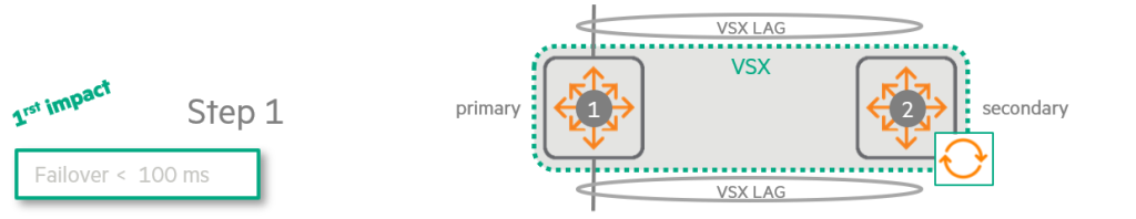
Once the download is complete Secondary switch reboots firstdo.
This causes all traffic to be forwarded to the failed over Primary switch.
VSX Primary Software Update Status: Waiting for VSX secondary to reboot complete VSX Secondary Software Update Status: Rebooting VSX ISL Status: Down Progress [###################1 TP5T#########.................................................]Step 2 – Primary switch standby
When the Secondary switch boots to the new version, the Primary switch Wait until the link-up delay timer expires.
This is to ensure that the Secondary switch has all the entries required to manage traffic.
VSX Primary Software Update Status: Waiting for VSX to complete
VSX Secondary Software Update Status: Image updated successfully
VSX ISL Status: Up
Progress [###################1 TP5T#########.................................................] switch-02# sh vsx status linkup-delay
Initial sync status : Completed Delay timer status : Running Linkup Delay time left : 2 minutes 22 seconds switch-02# sh vsx status linkup-delay
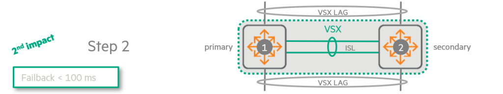
Initial sync status: Completed Delay timer status: Completed Linkup Delay time left:Step 3 – Reboot the Primary Switch
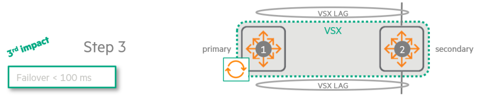
since Primary switch reboots itselfSo all traffic is forwarded to the Secondary switch.
VSX Primary Software Update Status: Waiting for VSX to complete VSX Secondary Software Update Status: Image updated successfully VSX ISL Status: Down Progress [###################1 TP5T#########.................................................] Second VSX system updated completely. Rebooting primary.Step 4 – Return to Primary
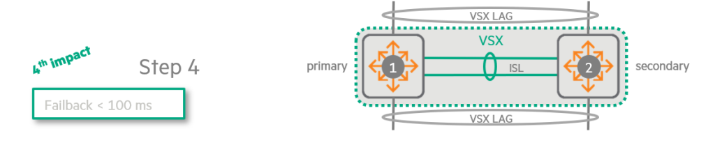
When the Primary reboots with the new version, it downloads all entries (routes, MAC addresses, ARP, etc.) from the Secondary switch.
After the link-up timer expires, Traffic is evenly distributed between the two switches.It will work.
switch-1# sh vsx status linkup-delay
Configured linkup delay-timer : 180 seconds Initial sync status : Completed Delay timer status : Running Linkup Delay time left : 1 minutes 58 seconds switch-1# sh vsx status linkup-delay
Configured linkup delay-timer: 180 seconds Initial sync status: Completed Delay timer status: Running Linkup Delay time left:
VSX in the Core Layer: Simplification and Optimization Strategies
Typically, VSX is deployed in the aggregation layer, but in certain environments, Implementing VSX in the core layerIt may be advantageous to do so.
If the aggregation layer only operates at L2
- Removing Spanning Tree: When the aggregation layer operates only as L2, VSX helps eliminate the need for spanning tree in the core layer via VSX LAG.
- Active-Active Gateway: VSX is a core switch for access VLANs. Active-Active Default Gateway Serviceto provide.
- Topology simplification: This approach simplifies the topology. Traffic flows to the core at Layer 2, and then all traffic is routed from the core. A simpler topology is Reduce failover timesYou can do it.
Additionally, HPE recommends using VSX for core switches in certain specific situations, including:.
- The network Uses IPv6 and supports many VRFs (Virtual Routing and Forwarding)If you have to
- Using OSPF as a routing protocol Optimizing OSPF performanceIf you have to
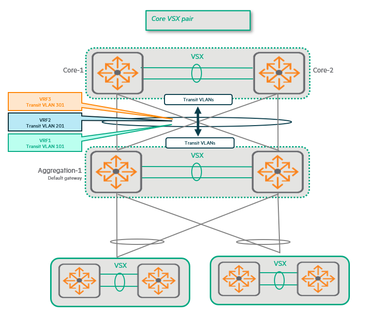
Advantages of VSX:
Each VRF requires its own transit VLAN and associated Switch Virtual Interface (SVI) for each VSX LAG.
At this time, by combining the core switches into VSX pairs, The number of VSX LAGs is halved.
This is It also reduces the number of transit VLANs and SVIs by half.
As the number of transit VLANs and SVIs decreases, Minimize and simplify the burden of SPF (Shortest Path First) calculations.You can do it.
VSX in the Core Layer: Fast Convergence or No Convergence
Another reason to use VSX in the core layer is Fast convergence or no convergence at all when a link between the core and aggregation layers fails.This advantage is especially noticeable when uplinks are used sparingly.
Standalone Core Switch vs. VSX Core Switch
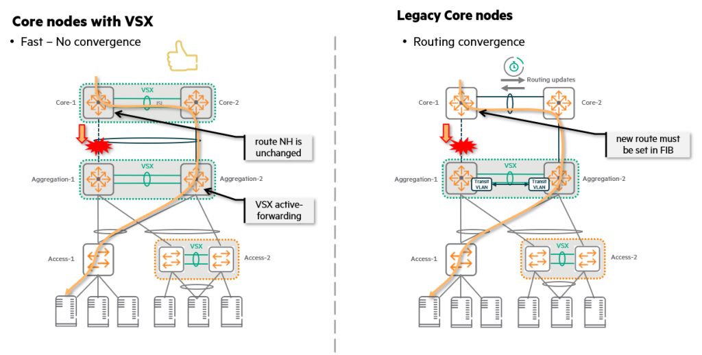
Looking at the right side of the above figure, we see a legacy situation where two independent switches operate as the core layer.
If the link between Core-1 and Aggregation-1 fails, Core-1 will attempt to find an alternate path. Update routing tableMust do.
This new route must be loaded into the switch's Forwarding Information Base (FIB), a time-consuming process.
Ultimately, this convergence process is bound to cause delays.
However, the left side of the figure shows a scenario where both the core and aggregation layers run VSX.
- merit: Even if one uplink between Core-1 and Aggregation-1 fails, No convergence required.
- reason: Because VSX LAG allows two switches to act as one logical device, The next hop is still the sameTherefore, there is no need to update the routing table.
In other words, it provides a significant advantage of ensuring service continuity by drastically reducing the failure recovery time without a convergence process in the event of a link failure.
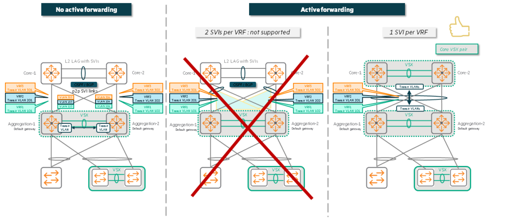
IPv6 and VSX Active Forwarding: Why SVI Limitations?
There is one important limitation when using VSX active forwarding in an IPv6 environment.
Only one SVI per VRF supports active forwarding.You can do it.
This is Because the link-local address of each SVI is the sameno see.
Interaction between Active Forwarding and IPv6
- Peer MAC address programming: When active forwarding is enabled, each switch MAC address of the peer switchProgram it to recognize your router's MAC address.
- Routing vs. Bridging: As a result, the switch Packets destined for the peer's IP address (and the peer's MAC address)When it receives a frame, instead of bridging it as in the traditional way, the hardware (HW) “routes” that frame to the peer. This process is the same even if both switches are on the same IP subnet/VLAN.
- IPv6 link-local address: Similarly, traffic arriving at VSX Switch B has a destination of VSX Switch A. Link-local addressIn this case, Switch B “routes” this traffic to Switch A over the ISL.
Why are we limited to a single SVI per VRF?
This way of working causes the following problems:
- Link-local address duplication: There are multiple SVIs within the same VRF and they are Same link-local address, the hardware's routing table cannot accept all the link-local addresses of multiple SVIs and be programmed for forwarding.
- Recognize only one: The hardware can handle multiple duplicate link-local addresses. Recognize only oneand can be programmed for forwarding. The remaining addresses are treated as duplicates.
So, when using IPv6, Enable active forwarding on only one SVI per VRF.Must do.
This ensures that the hardware's routing tables function correctly without confusion and that traffic is routed as expected.
Split-brain: Failure scenarios and protection mechanisms in VSX
Split-brain scenario
The picture below shows the connection between two VSX switches. ISL (Inter-Switch Link) is downIt shows.
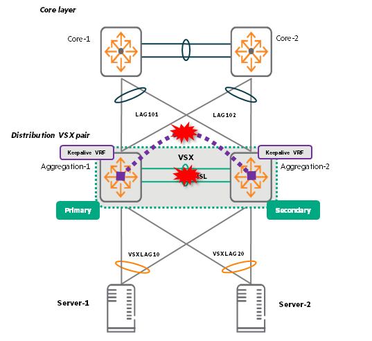
The two switches themselves are still alive, but they are no longer able to exchange information with each other, so they are out of sync.
This situation is called “split brain”., When the keepalive function is not activated It happens.
Keepalive detects whether a link between VSX switches is down or whether the VSX switch itself is not functioning. out-of-band mechanismThis prevents split-brain problems by providing a keepalive feature. When the keepalive feature is activated, it takes down the link between Agg2 and the access switch, forcing traffic to flow only from the access switch to Agg1.
Behavior according to ISL and keepalive status
| ISL situation | KeepAlive situation | result |
| Up (In-Sync) | Established | Normal operation. Traffic is forwarded normally and the system is protected from split brain. |
| Up (In-Sync) | Not established (Init | Normal operationHowever, the system is exposed to the risk of split brain. There is no protection mechanism in case of ISL failure. |
| Down (Out-of-Sync) | Established | Split brain prevention. Peers recognize that each other is still alive. The secondary switch shuts down its VSX LAG so that traffic flows only to the primary. |
| Down (Out-of-Sync) | Not established | The switch assumes that the peer is down. The system works, but 50% capacityForward traffic only to . For this assumption to be accurate, keepalive connections must be configured correctly. |
Behavior in case of ISL failure
Non-VSX LAG ports:
Not part of VSX LAG, but at least one orphan port1VLANs and associated SVIs belonging to (except ISL LAG) are not affected by the state (up/down) during ISL failure.
the first Before synchronization In case of ISL failure:
As long as the secondary VSX node has ports that are members of a VSX LAG, the associated SVIs for the VLANs carried by that VSX LAG will be available on the VSX secondary node, regardless of whether or not there are orphan ports. OFF/SHUT (Disable/Shutdown) It becomes a state.
After the first synchronization During the Link-up Delay Timer:
Secondary VSX switch의 Ports belonging to VSX LAGAs long as there is a VLAN SVI for that VSX LAG, Unconditionally disable (OFF/SHUT) Maintains the state. This rule will work regardless of whether there are any 'orphan ports' connected to that VLAN.
However, if both conditions are met, this SVI can be re-enabled (ON/UP).
- VSX LAG is included in the exclusion group:
linkup-delay-timer exclude lag-listThe VSX LAG in question must be excluded from the 'delay timer' by command. - The VLAN is not allowed on VSX LAGs outside the exclusion group: This VLAN should only allow traffic through VSX LAGs that belong to the 'Exclusion Group'.
This complex rule prevents all traffic from being routed to the rebooted switch while it is not yet fully ready. Forces the flow to only other switches (Primary) that have already been stabilizedSo, you can see it as a safety device to prevent traffic loss.
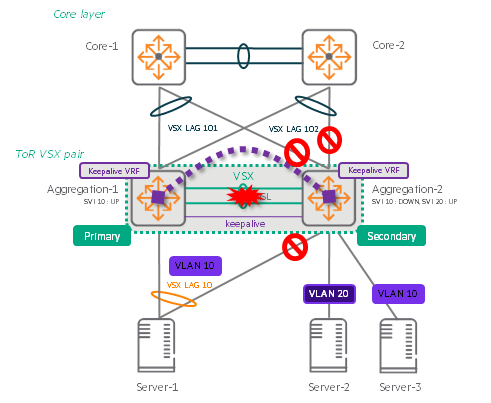
As you can see in the example picture above, when the ISL fails, the switches behave as follows:.
- VSX LAG related ports/SVI: Automatically deactivate. This is to prevent split brain situations.
If both switches try to process traffic while the ISL is down, data may get tangled or looped. - Ports/SVIs not associated with VSX LAG (Orphan ports): Continue to operate normally.
Above Server-2 and VLAN 20 are still turned on, but without an external uplink, this server cannot communicate with the external network and is isolated. - Example of disabling SVI: The port on Server-3 is still in 'UP' state, but the SVI of VLAN 10 that the port belongs to is in 'SHUT' state due to ISL failure. This is because the VLAN belongs to VSX LAG.
In conclusion, in the data center Always plan for redundant connectionsThe most important thing is to do it.
This will ensure that your service is not interrupted even if an ISL or switch fails.
Split Recovery

- purpose: Split recovery mode ensures that the Secondary switch activates its VSX LAG if keepalive fails while the ISL is out of sync.
- Basic actions: When the ISL goes out of sync and keepalives are triggered, the network takes down the Secondary VSX LAG and SVI.
- Problem: If keepalive fails and the split recovery mode, which is enabled by default, kicks in, the Secondary switch re-enables its VSX LAG and SVI.
In this case, the Primary switch is alive Asymmetric traffic flowBecause of Split brain occurs and traffic is lost.may lead to. - way out: To avoid this situation Disable split recovery modeIt is recommended to do so.
This is what we learned about VSX.
In modern data centers, high availability and resiliency are becoming increasingly important for business continuity.
We need more innovative and available approaches that go beyond simple link redundancy.
VSX is Live UpgradeThrough Non-stop updatesto enable, Keep AliveThrough Split BrainPrevents.
Maintain uninterrupted data center services with VSX features exclusive to AOS-CX switches.
- Downstream ports connected to a single VSX switch and not included in a VSX LAG (Link Aggregation Group) ↩︎