Wireless networks are designed primarily with coverage and capacity in mind.
When designing for WLAN coverage, the design should be based on the size of the area to be covered. If you're designing for coverage, aiming for 100% coverage across all areas, using higher-power APs will allow for a smaller number of APs.
On the other hand, designing a capacity-based WLAN requires considering the number of users, the applications they use, and the bandwidth requirements of those applications. Therefore, wireless networks designed for capacity-based design typically deploy a large number of APs operating at lower TX power.
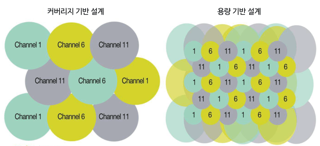
Operating at such low TX power allows for smaller cell sizes to allow each client to use higher speeds.
However, when configured with large cell sizes, such as coverage-based designs, it is suitable for low-density environments, such as those with only a few users using low-bandwidth devices in a large space.
In a typical office environment, it is recommended to design cells with small sizes so that only a few users can use each cell.
Channel Availability
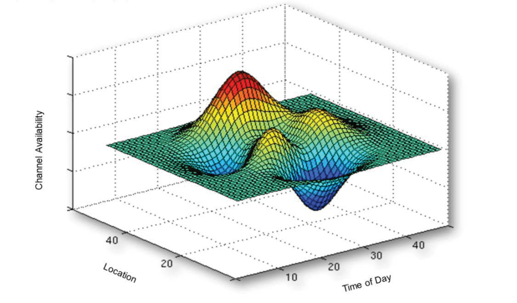
Channel availability is a key challenge for wireless networks, from design to troubleshooting, in any changing RF environment. RF interference from other 802.11 devices to non-802.11 devices, such as microwaves and Bluetooth devices, can cause wireless signal degradation, performance degradation, and connection drops.
This RF interference is unpredictable and unavoidable. It varies depending on the device (microwave oven, cordless phone), usage pattern (time of day), and location.
To provide stable Wi-Fi service, these RFs must be properly managed.
In general, 5GHz provides a cleaner wireless signal environment because it has more available channels, less co-channel interference, and less interference from non-802.11 devices. Therefore, most interference occurs on devices operating in the 2.4GHz band.
Now, let's look at what causes interference or poor communication that leads to poor performance in WLAN.
Wireless signal (frequency) problem
A common problem in wireless networks is slow throughput.
For example, a user might have a client device connected to an AP at a data rate of 54 Mbps, but in reality, the file transfer rate is only 5 Mbps. The most common reason for this is: Noisy RF environmentno see.
Raising the noise floor due to noise from other 802.11 signals or non-802.11 sources will cause the RF radio to retransmit data more frequently because this noise will block the signal.
Can you give me a simpler example?
Think about talking to a friend on the road as a noisy truck passes by.
Even when you're close to your friend, you might miss some of their voice. This is because the decibel (dB) of the truck is louder than their voice. If you mishear them and they start talking again, it's like retransmitting data on a wireless network.
These retransmissions ultimately reduce throughput because it takes more time to send the same amount of data.
Co-channel interference means that an AP is interfering with the signals of other APs.
Here we have non-802.11 interference signals. “noise“By following best practices for network design and deployment, you can mitigate co-channel interference. Alternatively, you can mitigate noise by identifying and eliminating the source of the noise. If this is not possible, you can avoid or make interference less sensitive by placing APs as far apart as possible and adjusting settings on the controller or APs.
Automatically managing AP channels via the WLAN controller is an effective defense against RF noise. The controller can automatically or dynamically change the AP channel from a noisy channel to a quiet channel with little interference.
RF WLAN interference
CCTV cameras, cordless phones, third-party APs, microwave ovens, Bluetooth, etc. Frequency Hopping Equipment is the most common source of wireless LAN interference. A spectrum analyzer is a very effective tool for identifying and locating potential interference sources.
Most devices that cause interference operate on 2.4Ghz rather than 5Ghz.
Another factor to watch out for is the device Duty Cycleno see.
When a noisy truck passes by on a busy highway, the dB level of the truck noise represents the RF Power or intensity of the interference, but the time the truck noise is heard is the duty cycle.
Imagine you have a friend standing on the side of the highway talking to you.
Depending on how loud the truck noise is and how long you listen, it will determine whether you can hear what your friend is saying.That is, even with the same dB of noise, the noise from a very fast-moving truck has less of an impact on noise than a slow-moving truck.
For example, in many environments, there are multiple Bluetooth devices, but Bluetooth typically has a low duty cycle. Therefore, this isn't a major issue and has minimal practical impact on the WLAN.
On the other hand, when the microwave is turned on, it has a duty cycle of 100% and interferes with most 2.4GHz wireless frequencies. Security cameras also have high duty cycles and, when set to high dB levels, can significantly impact WLANs.
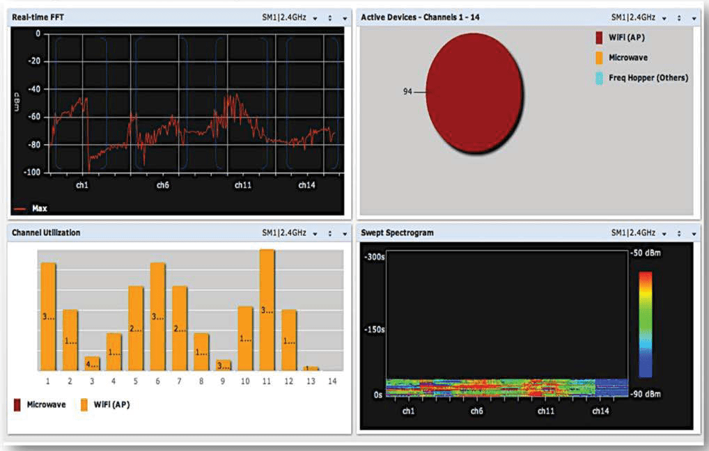
Aruba Spectrum Analyzer
The Aruba Spectrum Analyzer helps you "see" your RF environment. Any Aruba AP can be configured to function as a spectrum analyzer.
antenna technology
Antennas can perform both omnidirectional and directional functions. Devices such as AM/FM radios receive RF signals. receptionHowever, the devices of AM/FM broadcasting stations receive RF signals. forwardingJust do it.
Because devices on a wireless network both transmit and receive, the function of the antenna depends on what the device is currently doing.
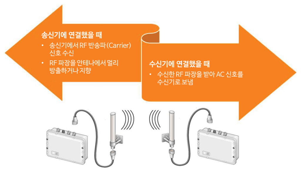
When a device transmits data, the antenna receives an oscillating carrier signal from the transmitter and radiates, or directs, RF waves from the antenna. When the device receives data, the antenna receives the RF signal and transmits an oscillating carrier signal to the receiver.
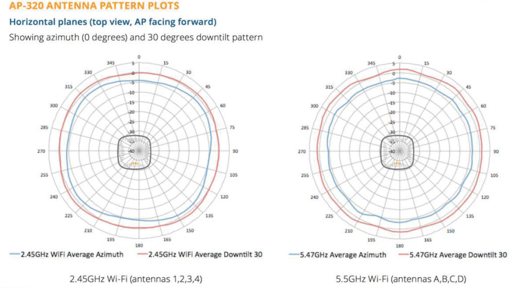
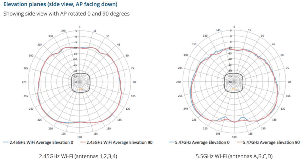
AP's radiation pattern
Most manufacturers provide radiation patterns for their APs that indicate horizontal and vertical coverage areas.
H-Plane is a plan view for horizontal coverage, and E-Plane is a side view (elevation view).
This will give you an idea of the intended coverage. Physical obstructions or RF interference may vary depending on where the client receives the signal from the AP.
The radiation pattern describes how the antenna shapes the AP's RF signal.
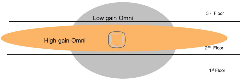
Antenna Gain
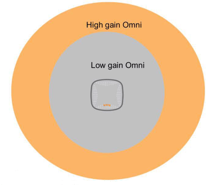
Antennas use passive gain to shape the signal's coverage area.
High Gain Omni pushes the signal wider horizontally, but loses coverage vertically.
High Gain Omni antennas are suitable for covering large areas, such as one floor of a building.
AP/Antenna Mounting Options
Regardless of the type or size of the area you want to service with Wi-Fi, APs with integrated (built-in) antennas can be mounted/installed in three ways.
Overhead coverage requires mounting APs on ceilings, walkways, roofs, or other surfaces directly above the users you want to serve.
- For side coverage, the AP can be mounted on a wall, pillar, or other support structure existing in the space.
- Floor coverage designs create picocells by mounting APs just below or above the floor of the coverage area.
- Ceiling mounting is common in office spaces, hospitals, etc., as the AP is unobtrusive and easy to install on the ceiling.
Ceiling mounting is the first choice unless the ceiling is too high or aesthetic reasons preclude mounting.
In most indoor office spaces, APs with built-in low-gain omni antennas are typically installed on the ceiling.
In high-density environments such as sports stadiums, they are sometimes installed on the floor.
Side mounting may be required if the ceiling is too high or difficult to access.
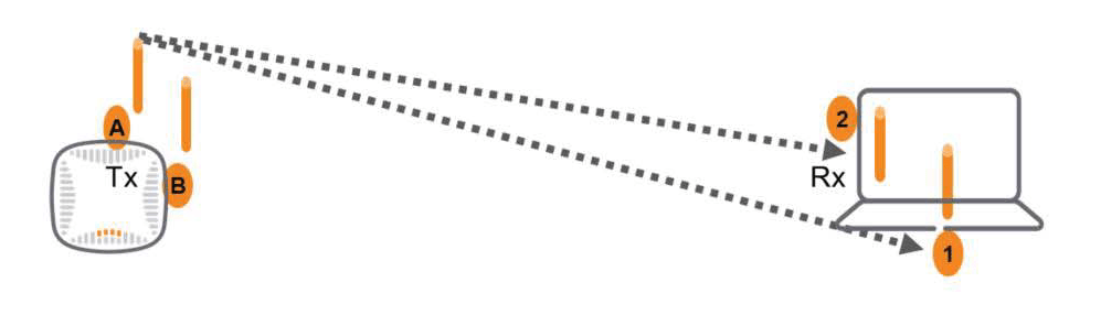
SISO (Single Input Single Output)
Traditional 802.11 networks, or wireless networks, use single-input/single-output (SISO) technology, allowing only one antenna to transmit or receive at a time. The transmitter sends a transmission to either the transmitting or receiving antenna for wireless signal processing.
Wireless radios select the signal with the best reception and discard the others. Therefore, only one data stream is effectively used for each transmission. This concept is known as antenna diversity.
This technique is similar to how we hear with two ears.
When we hear noise, we typically hear it with both ears and send it to the brain for processing. Having two ears helps us better hear sounds coming from one direction. It also allows us to detect the direction of the signal.
In this way, you can turn toward someone speaking and speak directly to them so they can hear you better. Antenna diversity is similar in that the antenna that last received the strongest signal is used to retransmit the signal.
Multipath Propagation Scenario
The problem with RF transmission is multipath propagation, which can cause signals to become corrupted or self-interfering, resulting in transmission losses.
Multipath propagation occurs when signals bounce off physical reflective objects in the vicinity.
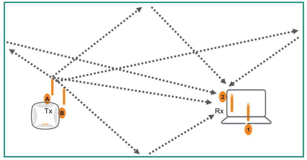
Additionally, if a receiving antenna is slightly out of phase with other antennas, it can receive multiple signals, potentially causing multipath propagation. This can result in the receiver being unable to receive signals due to multipath distortion caused by too many signals.
This ultimately results in retransmissions and low WLAN data throughput.
MIMO (Multiple Input Multiple Output)
However, the multipath impairment issue of SISO antenna systems can be turned into an advantage by using MIMO technology.
802.11n and 802.11ac use MIMO antenna technology to create two or more data streams transmitted from different antennas. These data streams, called spatial streams, provide significantly faster throughput than single-stream technology.
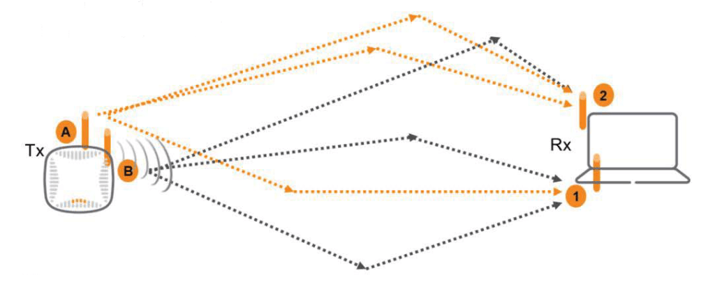
Multi-User MIMO (MU-MIMO)Through it, the AP can transmit data for different users along different spatial streams, bouncing them through the air along up to eight paths simultaneously.
Multiple Wi-Fi clients can now share a larger stream and antenna pool.
MU-MIMO is available in Phase 2 of the 802.11ac standard.
MIMO is specified by the number of Tx and Rx antennas, and can be expressed as an N x M matrix.
- N: Number of Tx antennas
- M: Number of Rx antennas
- Maximum in 802.11n is 4×4
- The maximum in 802.11ac is 8×8
In this post, we learned the basics about RF.
Since RF signals are the most fundamental part of understanding wireless LAN (WLAN), it is important to have a good understanding of RF signals, noise, interference, and antennas.
In the next post, we will learn about RF transmission strength and roaming.