Continuing from last time, I would like to learn about STP (Spanning Tree Protocol), and specifically RSTP (Rapid STP).
Let's look at the key factors that determine which ports the RSTP algorithm will use to forward traffic and which ports it won't.
- Bridge Identifier
- Bridge Protocol Data Unit
- Rapid Spanning Tree Port States
- Rapid Spanning Tree Port Cost
- Rapid Spanning Tree Port Roles
Bridge Identifier
Spanning Tree assigns each switch a unique identifier called a Bride ID.
This identifier consists of 2 bytes indicating the priority and 6 bytes indicating the MAC address.
The default priority is 32,768, so basically all switches have the same priority. However, each switch has a unique MAC address, so Each Bridge ID (BID) is unique.It will be done.
The default priority value for AOS-CX switches is 32,768no see.
Bridge Protocol Data Unit
All switches participating in the Spanning Tree algorithm exchange control messages called Bridge Protocol Data Units (BPDUs).
In the original 802.1d standard, BPDUs were generated only by the root switch and had to be propagated to other switches. This required slow Max Age and Forward Delay timers.
In RSTP, every switch generates a BPDU with current information every 2 seconds (the default Hello-time period).
Therefore, if a port does not receive a BPDU for three Hello-Timer cycles, the switch immediately recognizes that the connection with the neighboring device has been lost, expires the protocol information, and transitions to a new topology.
Since each switch initiates BPDUs, this becomes a true keep-alive mechanism. This ensures that fault detection takes no more than six seconds.
Port States
When building a Spanning Tree or applying a new topology after a failure, the switch must decide which ports should forward data and which ports should be disabled to prevent Layer 2 loops.
Spanning Tree uses port states to transition from a blocking port to a forwarding port. The table below summarizes the port states and their specific actions.
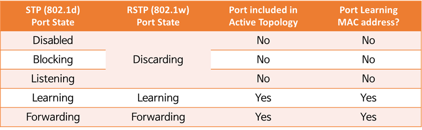
This table compares the Port States used in 802.1d and 802.1w.
The 802.1d standard takes 30 seconds to transition from Blocking to Forwarding: 15 seconds in the Listening state and 15 seconds in the Learning state.
One reason RSTP is more efficient than 802.1d is that ports transition from Discarding to Learning to Forwarding states more quickly.
※ reference: Blocking and Listening states are also deprecated in MSTP.
※ reference: In RSTP, the Learning state is temporary and is only used when a topology change occurs and the protocol needs to be re-implemented. Typical states are Discarding and Forwarding.
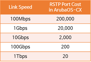
Path Cost
RSTP can have multiple paths from the root switch to the remaining switches (non-root switches). The cost varies depending on the link speed, and the optimal path is selected based on this cost.
The following table shows the default Cost values per port for AOS-CX.
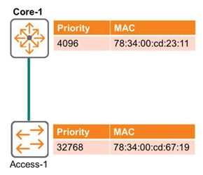
Considering the example in the following figure, intuitively, the best path for Access-1 might be considered the Direct Path. However, this is a 1Gbps link with a cost of 20,000.
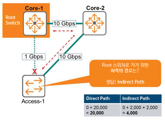
The Indirect Path that connects Access-1 via Core-2 has two 10Gbps links, each with a Cost of 2,000.
That is, 2,000 + 2,000 = 4,000이 20,000Since there are far fewer of them, the Indirect Path is the best route.
Port Role – Designated and Root
Switches using 802.1w RSTP do not have a view of the overall topology. Therefore, each switch exchanges BPDUs indicating its proximity to the root switch to establish and maintain a loop-free topology.
Here, BPDUs help the switch calculate the correct port role for each port.
All ports on the root switch are designated ports. The root switch acts as the "boss" of the domain and does not block any ports. Only non-designated ports need to be addressed.
The figure below is an example topology for the role of each port.
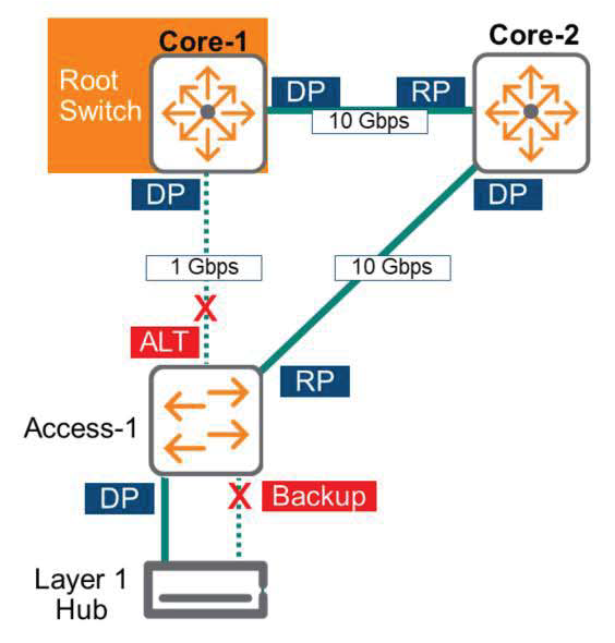
The roles of each port are summarized with pictures as follows.
- Designated Port (DP)
- Port closest to the root switch
- All ports on the root switch
- Port State: Forwarding
- Root Port (RP)
- A port on a switch that is closer to the root switch
- Port located on the best path to the root switch
- Port State: Forwarding
- Alternative Port (ALT)
- A port that is not the port closest to the root switch (RP) on the link
- This link does not provide the best path to Root on the switch.
- Ports are not connected to the same switch – there is no loop on its own.
- If there is a problem with the Active link, change to Root Port (RP).
- Port State: Discarding
- Backup Port
- A port that is not the port closest to the root switch (RP) on the link
- This link does not provide the best path to Root on the switch.
- Ports are connected to the same switch – a loop exists due to a switch or Layer 1 Hub
- If there is a problem with the existing Designated Port, the Backup Port is changed to the Designated Port (DP).
When a Layer 1 Hub is placed in a topology, loops may occur.
※reference: Care must be taken not to place Layer 1 Hubs in an RSTP topology.