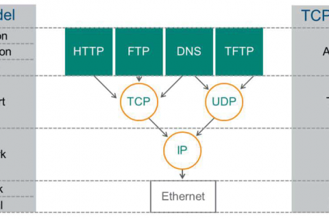
Earlier, when we looked at technologies represented in Layer 2, such as VLAN and 802.1Q, we also mentioned frames.
Previous PostWe have also described Ethernet frames, which correspond to Layer 2 in the OSI layer.
So today, I want to look at how this frame works when doing Layer 2 communication with a real-world example.
First, let's look at communication between two devices going back and forth across multiple switches, assuming they are in the same VLAN.
Basic scenario configuration
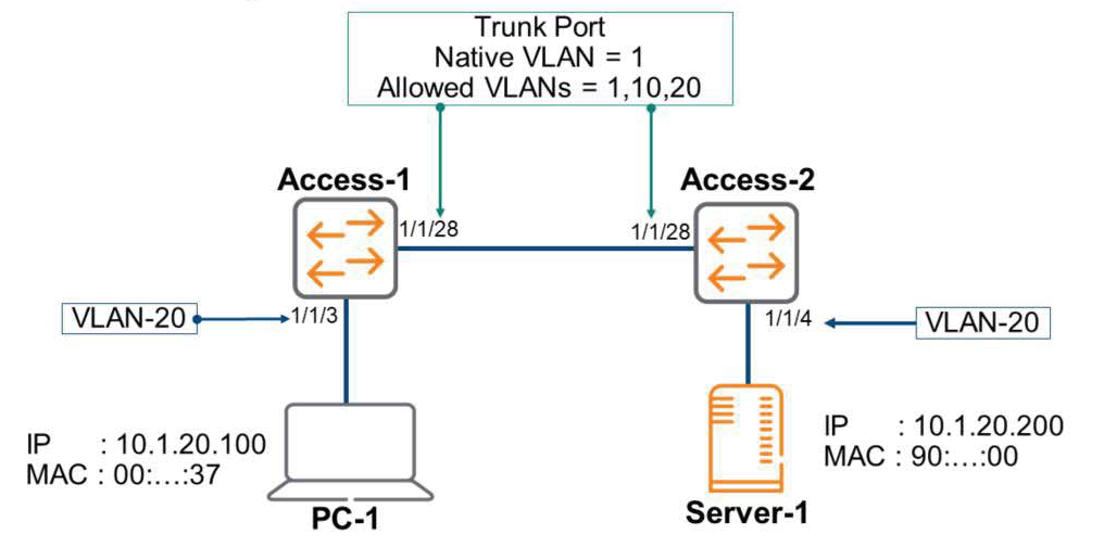
Looking at the picture above, PC-1 and Server-1 each have their IP addresses properly set, and each switch has VLANs 1, 10, and 20 set up. A trunk port is configured between the two switches, allowing traffic for VLANs 1, 10, and 20 to communicate.
PC-1 is connected to port 1/1/3 of the Access-1 switch with VLAN 20, and Server-1 is connected to port 1/1/4 of the Access-2 switch with VLAN 20.
Assuming that there has been no communication between PC-1 and Server-1 yet, let's look at how frames are transmitted in a scenario where PC-1 downloads a file from Server-1 via FTP.
Starting an FTP session
A user on PC-1 opens a browser and enters the IP address of Server-1.
ftp://10.1.20.200
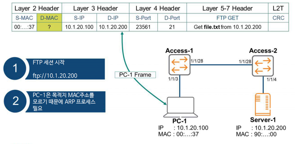
Even though PC-1 knows the destination IP address, it doesn't yet know the MAC address mapped to that IP address, so the ARP process must be performed. Furthermore, PC-1 knows all the remaining Layer 2 information, including Layers 3 through 7, which are required to create the frame.
ARP Request
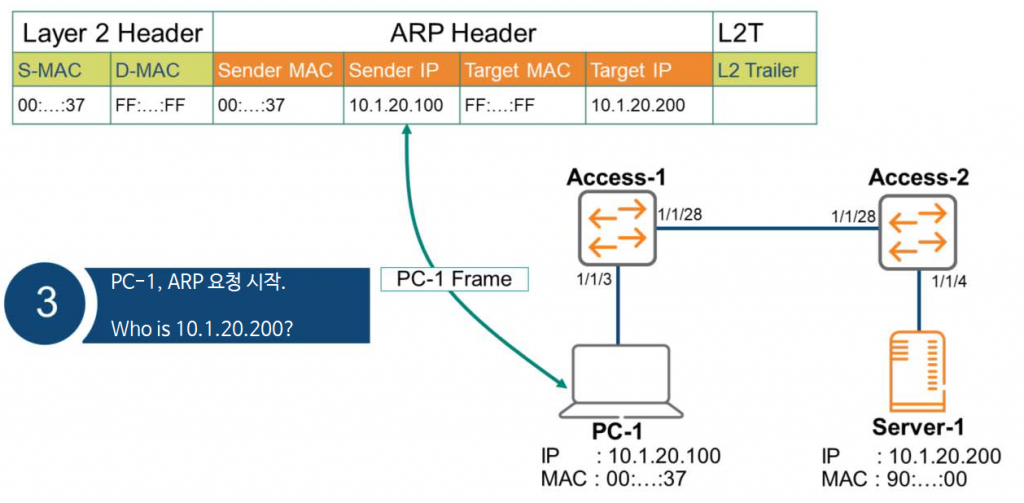
PC-1 creates an ARP request message for the ARP process and broadcasts the message to the entire Layer 2 using the destination MAC address (FF:FF:FF:FF:FF:FF).
Sending ARP broadcast
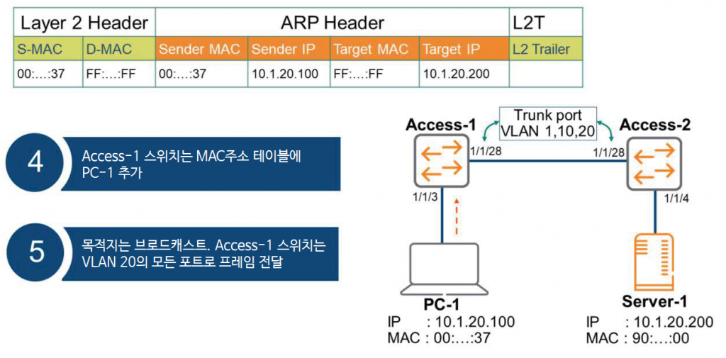
The Access-1 switch receives the message and enters the 1/1/3 port and the PC-1 MAC address into its MAC address table.
Additionally, since the ARP request is a broadcast, the frame is flooded (sent) to all ports corresponding to VLAN 20. At this time, it is forwarded to the Access-2 switch via 1/1/28, which is connected to the trunk port.
dot1q – Tagging
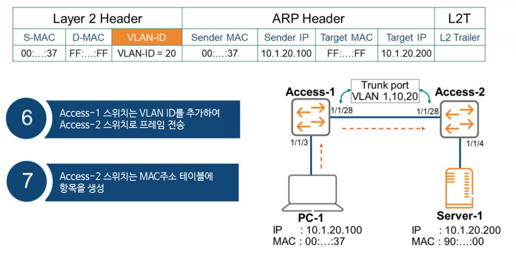
Since port 1/1/28 on the Access-1 switch is configured as a trunk port, it uses the dot1q tag with VLAN ID = 20 when forwarding the frame. The Access-2 switch receives the frame and creates an entry in its MAC address table.
Untagged frame delivery
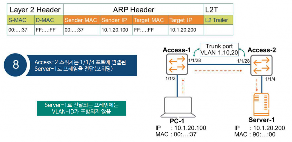
The Access-2 switch forwards the frame to all ports mapped to VLAN 20. The frame is forwarded to port 1/1/4, which has VLAN 20 configured. Because this interface is not a trunk port, the frame forwarded to Server-1 does not contain 802.1q tags, such as the VLAN ID.
ARP Reply
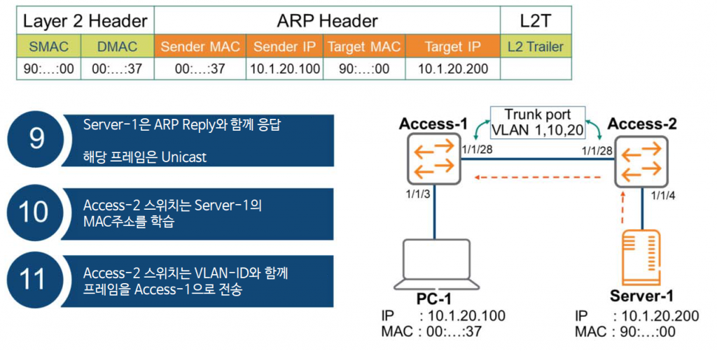
Server-1 receives the ARP request and generates an ARP reply. Since PC-2 knows the source MAC address, this frame is communicated unicast.
Now, the Access-2 switch must process the ARP Reply message. First, it learns the MAC address of Server-1 and enters an entry in its MAC address table. Then, it forwards the frame, including the VLAN ID, to the Access-1 switch.
Receive ARP message
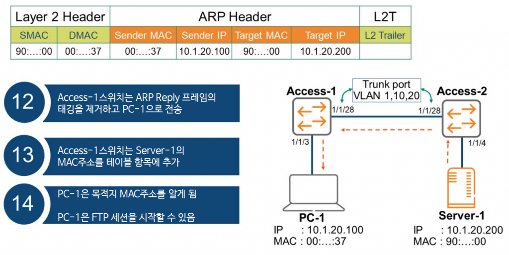
The Access-1 switch forwards an ARP Reply frame to PC-1. As expected, since port 1/1/3 is not a trunk port, it removes the 802.1q tag and forwards the frame. The Access-1 switch then adds Server-1's MAC address to its MAC address table and ARP table.
Now that PC-1 knows the MAC address of Server-1, it can complete the Ethernet frame and download the file via FTP.
So, we've looked at how the VLAN, ARP, and 802.1Q processes discussed in the previous post actually work and operate. I hope this simple example will help you understand the concepts more clearly.
It is important to have a solid understanding of VLANs and 802.1Q as they are used extensively in the field.
It would be very helpful to set up a simple practice environment and directly view the contents of the frames using Wireshark or similar.