Network communications are crucial to IT infrastructure, often having a significant impact on critical services.
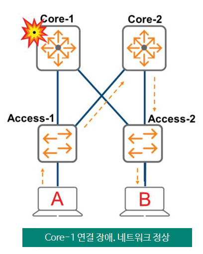
If there is only one path to the Core-1 switch as shown below, if the link to the Core-1 switch among the two access switches is broken, the network will be disconnected, and Host A and Host B will not be able to communicate with each other.
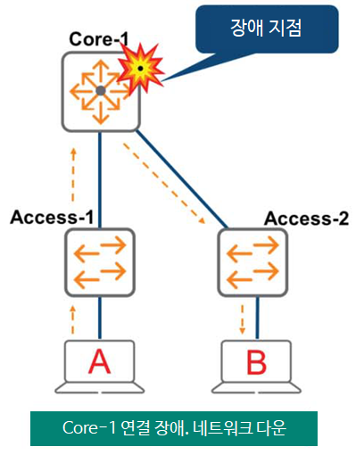
The way to solve this is to add one Core switch as shown in the figure below.
Even if the Core-1 switch fails, network communication will still be possible. Host A and Host B can communicate with each other through the Core-2 switch. This connection is called redundancy or a redundant link.
However, while this redundant configuration solves the single failure issue, it creates another problem.
Layer 2 Loop
Connecting Layer 2 switches in a link redundancy configuration creates a Layer 2 loop. A loop is also created when connecting a cable from one port on a switch to another port on the same switch.
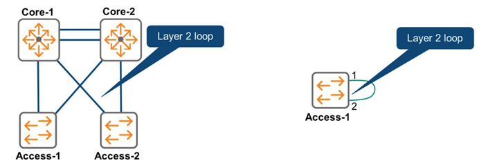
When a loop like this is created, it can cause serious problems in the network if not handled properly, as shown below.
- Broadcast Storm
- Multiple Frame Copy
- Instability of MAC address table
Layer 2 Loop – Broadcast Storm
Previous PostIn , the switch is said to send the broadcast packet to all interfaces in the same VLAN except the port that received it (the ingress port). This causes problems in a redundant loop network like the one shown in the figure.

- Assume Host A sends a broadcast frame.
- Switch Access-1 receives and forwards this frame (Copy 1)
- The Core-1 and Core-2 switches receive this and pass it back to each other (Copy 2)
- The Core-1 and Core-2 switches each receive a second copy (Copy 2) and forward it to another port (Copy 3).
- Access-1 receives the third copy (Copy 3) and repeats the resending.
※ This frame will circulate on the network forever.
In the operational world of network devices and endpoints, nearly all devices often send broadcast frames multiple times per minute. In a loop environment, broadcast frames from all devices would circulate endlessly across the network.
As the number of broadcast frames circulating increases and the number of copies increases accordingly, all available bandwidth and CPU resources will be used to process broadcast traffic. Consequently, there will be a shortage of resources to process normal data communication frames. Eventually, the network becomes unusable.
Layer 2 Loop – Multiple Frame Copy
Although the switch may broadcast to all ports in the VLAN, Learn about Forwarding TableWe also discussed that the same thing is done to send unicast traffic to a destination that is not yet known.
When a switch receives a unicast packet addressed to a destination MAC address, if that MAC address isn't already in the MAC address table, the switch forwards the frame to all ports in the VLAN. This also circulates the frame, wasting CPU resources.
There are other problems as well.
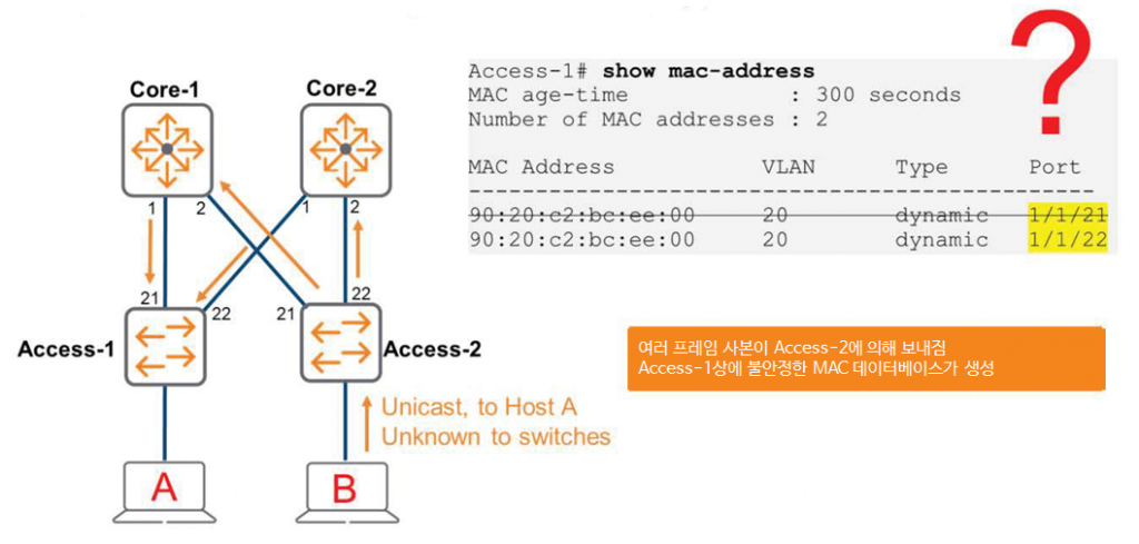
Let's assume Host B sends a frame to Host A.
Since the Access-2 switch does not yet know Host A's MAC address, it forwards this frame to Port 21 and Port 22.
At this time, both the Core-1 switch and the Core-2 switch receive the frame containing the source MAC address 90:….:00 and copy the frame back to the Access-1 switch for forwarding.
From the Access-1 switch's perspective, it will think it can communicate with Host B via Port 21 or Port 22. This is confusing, as it appears as if Host B exists in two places. However, Host B exists in only one place. Ultimately, the multiple frame copies generated by Access-2 will corrupt Access-1's MAC address database.
As you can see, this poses a very serious problem. While link redundancy is necessary for stability, this redundancy can also cause the entire network to collapse and go down.
The solution to these problems is the Spanning Tree Protocol (STP). Invented in 1984 by Ms. Radio Perlman, the algorithm for this protocol reportedly took only a few hours to develop.
In the next post, we will learn more about Spanning Tree Protocol.