In the last post, we learned what RoCE is and why it is needed.
So, this time, let's learn how to implement RoCE on the AOS-CX switch.
To configure RoCEv2 on HPE Aruba Neworking CX switches, you will need the following:.
- DCB Ethernet and DCB-enabled switches to ensure a lossless network fabric
- PFC to prevent packet loss
- ETS protecting traffic classes (TC)
- ECN (& PFC) over L3 link
- NIC that supports RoCE
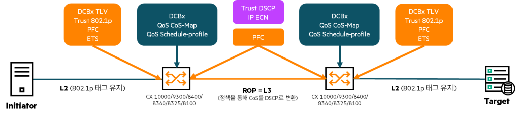
As of March 2025, supported switches are the CX 10000, 9300, 8400, 8360, 8325, and 8100 switch series.

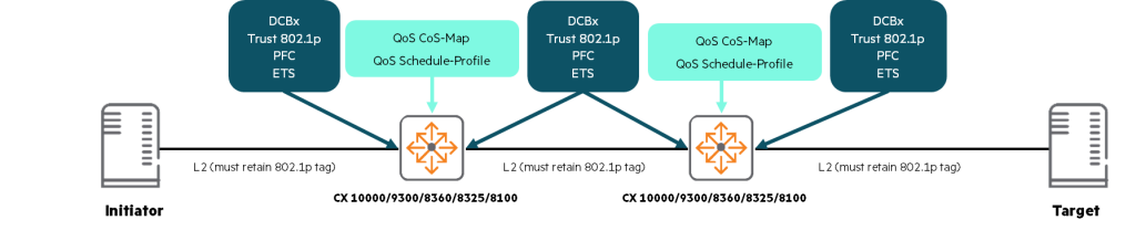
In a RoCE-based solution, the host (initiator or target) is configured to forward lossless traffic to the connected switch with the correct 802.11p or DSCP values. Switches in the fabric utilize the L2 links to the initiator and target, as well as the L3 links between the switches.
How to configure a RoCEv2 switch
To implement RoCEv2 on the AOS-CX switch, follow these steps:.
- Enable LLDP and DCBx
- QoS Pool Settings (CX8325/9300/10000)
- Configure QoS Queue Profile
(For best performance, configure two queue profiles - one queue for lossy traffic and the other for lossless traffic) - Configure and apply QoS Queue/Schedule profiles
- Setting up Global Trust
- Setting up PFC on interfaces that require lossless Ethernet
- Flow-Control Watchdog Settings
- Application TLV (Type-Length-Value) settings
- Setting ECN threshold profiles
1. Activate LLDP and DCBx Config
※ Notes on DCBx
- DCBx is supported on CX8100/8360/8325/8400/9300/10000 series.
- DCBx is disabled by default.
- LLDP must be enabled on interfaces that support DCBx.
- DCBx is only supported on physical interfaces because it relies on LLDP.
And it is not supported in management or logical interfaces.- AOS-CX supports IEEE and CEE versions of DCBx.
- AOS-CX signals DCBx by setting the 'will bit' to 0 in all TLVs.
This informs the peer that the switch is not willing to change its configuration to match the peer's configuration.- If the peer device does not support IEEE DCBx, show dcbx It is displayed in the interface output.
- LLDP DCBx can be enabled globally or at the interface level.
In fact, the configuration method of AOS-CX is as follows.
- Enable LLDP (default: enabled)
switch(config)# lldp- Check LLDP status
switch(config)# show lldp configuration

LLDP Global Configuration ======================== LLDP Enabled                 : Yes
LLDP Transmit Interval: 30 LLDP Hold Time Multiplier: 4 LLDP Transmit Delay Interval: 2 LLDP Reinit Time Interval: 2 LLDP Trap Enabled : No- Enable DCBx globally with default IEEE version (default: disabled)
switch(config)# lldp dcbx- Select a specific DCBx version (the example below uses the CEE version)
switch(config)# lldp dcbx version cee- Enable DCBx on the interface (enabled globally, all enabled by default)
switch(config-if)# lldp dcbx- Check DCBx status
switch(config-if)# show dcbx interface 1/1/3
DCBx admin state: enabled
DCBx operational state: inactive DCBx version: local = ieee, remote=NONE
PFC operational state: inactive
2. QoS Pool Settings (CX8325/9300/10000)
The QoS Pool option on the CX 8325/9300/10000 platforms allows you to create a dedicated packet buffer pool for lossless traffic.
The QoS Pool command allows you to create a lossless pool size, a headroom buffer associated with the pool, and a priority mapped to that pool.
The size of the lossless pool is a percentage of the total buffer memory available on the device.
Headroom Pool memory is allocated from the lossless pool and is used to store packets that arrive at a port after a pause has been declared.
- QoS Pool Settings
switch(config)# qos pool {1 | 2 | 3} lossless size percent headroom kbytes prioritiesThe description of each parameter for configuring the QoS Pool is as follows:.
| Parameter | explanation |
|---|---|
| {1|3} | Define the lossless pool number Possible numbers are 1 to 3 (for CX 8325, 9300, 10000 switches) NOTE: For CX 8100, 8360, 8400, only 1 Pool is possible. |
| <PERCENT> | Specify the size of the lossless pool in percentages – Default: 40.6 – range: 10~90%. Percentage of packet buffer memory to allocate to this Pool (integer format) or – range: 10.00~90.00%: Percentage of packet buffer memory to allocate to this Pool (in decimal format) |
| <factory-default> | Specify the default lossless pool or headroom buffer size. |
| <PRIORITY> | Specify the PFC priority to be mapped to the pool – range: 0~7 To map multiple priorities, separate them with commas (e.g. 1, 3, 6) |
<Example 1> Configure one QoS Pool and assign a single packet priority (4)
switch(config)# qos pool 1 lossless size 60 percent headroom 2048 kbytes priorities 4<Example 2> Configure one QoS Pool and assign two packet priorities (3, 4)
switch(config)# qos pool 1 lossless size 60 percent headroom 2048 kbytes priorities 3,4Once the new Pool settings are created, configure startup-configIt will not take effect until you save it and reboot the switch.
To monitor QoS pool usage: show qos pool Just run the command.
switch# show qos pool statistics
Packet-Buffer Pool Statistics Recent-Peak Interval: 1427 seconds Packet Buffer Pools Total Size Peak Use Recent Peak Current Use ------------------- ---------- ---------- ----------- ----------- Lossy Pool 19036 20 20 0 Lossless Pool 1 8679 5579 5579 0 Headroom 1 3078 0 0 0 Lossless Pool 2 0 0 0 0 Headroom 2 0 0 0 0
3. Configure QoS Queue Profile
- A QoS Queue profile maps local priorities to queues.
- CoS-Map defines a mapping of 802.1p priority codes to local priorities.
- The relationship between QoS queue profiles for lossless Ethernet and CoS1 Map and DSCP2 It's a map.
- Both Maps will have factory defaults applied at system startup.
switch# show qos cos-map default
code_point local_priority color name ---------- -------------- ------- ---- 0 1 green Best_Effort 1 0 green Background 2 2 green Excellent_Effort 3 3 green Critical_Applications 4 4 green Video 5 5 green Voice 6 6 green Internetwork_Control 7 7 green Network_Control
switch# show qos dscp-map
DSCP code_point local_priority mpls_exp color name -------- ---------- -------------- -------- ------- ---- 000000 0 1 0 green CS0 Codepoints 1-7 removed for brevity 001000 8 0 1 green CS1 Codepoints 9-15 removed for brevity 010000 16 2 2 green CS2 Codepoints 17-23 removed for brevity 011000 24 3 3 green CS3 Codepoints 25-31 removed for brevity 100000 32 4 4 green CS4 Codepoints 33-39 removed for brevity 101000 40 5 5 green CS5 Codepoints 40-47 removed for brevity 110000 48 6 6 green CS6 Codepoints 48-55 removed for brevity 111000 56 7 7 green CS7 Codepoints 57-63 removed for brevity- The queue profile determines whether a queue is assigned a local priority.
- You must configure one Queue profile for every port.
- Code points used in PFC must be assigned a unique local priority.
(i.e., no other code points can be assigned to the local priority used for PFC) - While traffic is flowing, you cannot change the CoS/queue map for a PFC PCP or change the queues that PFC traffic is using.
- The Two Queue solution is preferred because it provides the best queue depth for burst absorption.
Configure a CoS-Map queue. Below is an example of a 2-Queue model.
Local priority 4 is the only traffic mapped to Queue 1 and is configurable as lossless.
switch(config)# qos queue-profile que-pro1
switch(config-queue)# map queue 0 local-priority 0
switch(config-queue)# map queue 0 local-priority 1
switch(config-queue)# map queue 0 local-priority 2
switch(config-queue)# map queue 0 local-priority 3
switch(config-queue)# map queue 1 local-priority 4
switch(config-queue)# map queue 0 local-priority 5
switch(config-queue)# map queue 0 local-priority 6
switch(config-queue)# map queue 0 local-priority 7
switch(config)# show qos queue-profile que-pro1
queue_num local_priorities name --------- ---------------- ---- 0 0,1,2,3,5,6,7 1 4When using local priorities for lossless traffic, it is recommended not to assign multiple local priorities to the same queue.
Note that, regardless of queue configuration, lossless queues typically only hold packets buffered in the lossless pool, so lost packets in other queues do not negatively impact buffer availability. As shown in the example below, the tradeoff for reducing the number of queues is the loss of the ability to configure differentiated scheduling/servicing for various types of "other" traffic.
4. Configure and apply QoS Queue/Schedule profiles
The QoS Schedule profile determines the order in which Queues transmit packets and the amount of service defined for each Queue.
The profile will always be applied to all interfaces, either using user configuration or default (Factory-default).
The configuration method allows you to specify a global Schedule profile for all ports and specific Schedule profiles per interface.
If both a global profile and an interface-specific profile are configured, the interface-specific Schedule profile is used.
Interfaces carrying lossless traffic must have a Schedule profile configured to allocate bandwidth appropriate for the lossless flow environment.
CX switches are automatically provisioned by factory default with the Schedule profile, which assigns WFQ to all Queues with a weight of 1.3 and DWRR4 Assign a scheduling algorithm.
Additionally, the CX switch has a predefined Strict Schedule profile that services queues in descending priority order (from 7 to 0) until each queue is empty. This Strict Schedule profile is not enabled by default, but is available on all interfaces and in all queue profiles.
The example below shows ETS configuration in a 2-Queue environment.
switch(config)# qos schedule-profile sch-pro1
switch(config-schedule)# dwrr queue 0 weight 15
switch(config-schedule)# dwrr queue 1 weight 15
This setting uses weights to set the amount of bandwidth available to each Queue.
The above example setup will apply 50% of bandwidth to both Queue 0 and Queue 1.
switch(config)# show qos schedule-profile sch-pro1
queue_num alogrithm weight max-bandwidth_kbps --------- ------------- ------ ------------------ 0 dwrr 15 1 dwrr 15
Apply Schedule settings to the Queue profile.
switch(config)# apply qos queue-profile que-pro1 schedule-profile sch-pro1Configuring a Qos Schedule profile must follow these guidelines:.
- Each port can have its own Schedule Profile.
- Queues determine the order in which packets are transmitted and the amount of service defined for each queue.
- The factory-default and strict profiles cannot be deleted or changed.
- The applied schedule profile can be changed with limitations.
Any other changes will disable the schedule profile and revert to the factory default profile until you modify the profile:
(weight of dwrr queue, bandwidth of strict profile)
For more information about Schedule profiles, please see the CX Guide article.
5. Setting up Global Trust
Appropriate Trust configuration must be applied to the relevant ports.
For RoCE-based solutions that rely primarily on 802.1p marking, users must ensure that the marking is trusted.
Therefore, it is recommended to set the Global Trust mode to CoS.
Setting the Global Trust mode to CoS applies to all interfaces that do not already have an individual trust mode configured.
Then, DSCP overrides can be applied to all L3 interfaces that do not have 802.1p tags.
The following CLI command shows how to configure Global Trust.
switch(config)# qos trust
cos Trust 802.1p priority and preserve DSCP or IP-ToS dscp Trust DSCP and remark the 802.1p priority to match
For RoCEv2, when transmitting lossless packets, either trust CoS or trust DSCP can be used, depending on how it is set on the endpoint.
If there is no VLAN tag, trust DSCP is used.
When VLAN tags are present, the user can choose between trust CoS or trust DSCP, depending on which packet field the endpoint is known to fill with the correct packet priority.
How to check if Global Trust settings have been applied show qost trust Use the command.
switch(config)# show qos trust
qos trust cos
switch(config)# show qos trust
qos trust dscp6. PFC settings
PFC enables flow control for integrated 802.3 Ethernet media interfaces in LAN and SAN technologies.
PFC is designed to prevent packets of a specific priority from being dropped due to device congestion when bandwidth contention occurs on a link. This allows loss-sensitive protocols, such as RoCE, to coexist with loss-tolerant protocols within the same unified fabric.
CX switches that support RoCE support PFC, but a caveat for PFC (as well as LLFC RxTx) on the CX 10000 switches is that flows arriving on port priorities configured for PFC will not be visible to the distributed service processor.
Therefore, these flows are not visible to the monitoring and configured rules.
Before configuring a PFC, keep the following in mind:.
- To ensure lossless operation in a given environment, PFC must be enabled on all endpoints and switches in the traffic path.
- PCP 0 is not available for PFC lossless queue.
Additionally, we recommend not configuring PFC on PCP 7, as some switches generate protocol and control packets that use this priority. If these packets get stuck in the paused queue, protocol-related issues may occur. - Priority for all traffic control must first be mapped to the lossless Pool using the QoS Pool command.
- PFC must be configured at both ends of the link where lossless networking is required.
- On L3 interfaces, PFC must use DSCP values for classification.
When using VLAN tags, PFC uses 802.1Q tags instead of DSCP values.
On CX 10000, 8325 switches, when the interface priority is configured as PFC, the packet field used to determine whether a packet is lost or lossless may be different from the packet field used for local priority classification (based on the configured Trust Mode).
While QoS reliability mode determines the local priority (and therefore the transmission queue), the local priority value is only used to determine the loss or losslessness characteristics of packets for untagged frames.
When configuring PFC on a CX switch, you should be aware of the following:.
- The CX 10000, 9300, and 8325 switches can configure up to seven lossless PFC priorities per interface.
- The CX 8360 and 8100 switches can configure two lossless PFC priorities per interface.
- The CX 8400 switch can configure one lossless PFC priority per interface.
When you configure PFC on an interface, packets arriving on that interface marked with that priority should not be dropped.
The following CLI command enables PFC for priority 4 packets arriving on interface 1/1/2.
switch(config)# interface 1/1/2
switch(config-if)# flow-control priority 4
After setting PFC, you can check the application status using the show command.
switch(config)# show dcbx interface 1/1/2
DCBx admin state: enabled
DCBx operation state: active

Priority Flow Control (PFC) ---------------------------
Operational state: active

Local advertisement: Willing : No
    MacSec ByPass Capability: No
    Max traffic classes: 1 Priority Enabled 0 False 1 False 2 False 3 False
    4 True
    5 False 6 False 7 False
7. Flow-control Watchdog Settings
The Flow-control Watchdog feature monitors PFC-enabled queues on physical interfaces.
If the lossless queue is paused for too long (i.e., lossless packets in the queue are not transmitted), congestion in the lossless buffers across the network can occur. To prevent this, the egress lossless queue is monitored to ensure that no transmissions occur within a globally specified timeout period.
When the conditions are met, Flow Control monitoring is triggered for the affected Queue, which performs the following actions:.
- The interface's Flow-Control Watchdog timeout counter is incremented.
- All packets occupying the affected Queue are dropped.
- New packet arrivals to the affected Queue are dropped.
After the configured Resume Interval has elapsed after the trigger, the Queue returns to normal operation.
Flow-Control Watchdog is only supported on interfaces with PFC configured.
When Flow-Control Watchdog is enabled, it is enabled on all lossless queues on the port.
This feature is only supported by CX 10000, 9300, and 8325.
Here's how to configure the Flow-Control Watchdog:.
- Enabling Flow-Control Watchdog on the interface
switch(config)# flow-control watchdog- Set a timeout period for the interface
switch(config)# flow-control watchdog timeout resume- no The command can be used to revert the configured Flow-Control Watchdog.
switch(config)# no flow-control watchdog timeout resumePlease refer to the following for each parameter for setting for each time.
| Parameters | explanation |
|---|---|
| timeout | Specifies the time (in milliseconds) that the Queue must pause to trigger the Watchdog. – range: 10~1500 milliseconds – Default: 100 milliseconds |
| resume | Specifies the time (in milliseconds) that the queue remains triggered. – range: 10~1500 milliseconds – Default: 100 milliseconds |
8. DCBx Application TLV Settings
The Type Length Value (TLV) of a DCBx application is announced in the DCBx Application Priority message sent to the connected device.
These messages instruct the DCBx peer to forward application traffic at a configured priority so that the network can properly receive and queue the traffic. Multiple applications can be configured in this manner.
If the connected device does not comply with the DCBx Application TLV, you must manually configure the device to correctly display traffic.
To configure application priority for DCBx advertisements, set:.
switch(config)# dcbx application {ISCSI | TCP-SCTP | TCP-SCTP-UDP | UDP | ether } priorityThe following example shows the command to configure DCBx to advertise iSCSI traffic using priority 4.
switch(config)# dcbx appliaction iscsi priority 4Here is an example DCBx configuration to advertise tcp-sctp port 860 traffic using priority 4:.
switch(config)# dcbx application tcp-sctp 860 priority 49. Setting the ECN threshold profile
Explicit Congestion Notification (ECN) allows TCP/IP-based networks to send notifications of network congestion between ECN-enabled senders and ECN-enabled receivers. The ECN Threshold profile sets thresholds for individual queue utilization, which trigger actions (i.e., marking packets as ECN-enabled).
ECN configuration allows users to adjust various parameters to achieve optimal performance.
Using ECN and PFC together can improve network-wide performance by providing feedback on congestion occurring at endpoints before PFC is needed to prevent buffer overflows.
The following are guidelines for ECN configuration.
- Configure a Queue to transmit delay-sensitive traffic
- You can configure as many Queues as you want in your profile.
- An unconfigured Queue means that no threshold action occurs.
- Threshold profiles are not created or configured by default.
- For ECN to work, all switches in the path between two ECN-enabled endpoints must have ECN enabled.
This phenomenon occurs when the ECN threshold is configured too high or too low.
- If the ECN threshold is configured too high, the threshold may not be reached before a PFC Pause occurs to prevent losses.
- If you configure the ECN threshold too low, performance will degrade because there won't be enough packets buffered on the network to keep traffic flowing at line rate when needed.
The ECN threshold can be configured from a minimum of 500kB to a maximum of 1500kB, and depending on link speed, round-trip latency, and interface oversubscription in the data path, this value can be increased to allow more buffer usage before notifying that there is congestion.
When configuring an ECN, keep the following in mind:.
- When the queue exceeds the min-threshold limit, the ECN operation marks ECN-capable transmission (ECT) packets as CE based on the marking probability at the current queue size, which increases linearly from 1 to 100% between the min-threshold and max-threshold.
- When the queue exceeds the max-threshold limit, the ECN behavior is to mark all ECT packets as CE.
- IP ECN is supported only in the underlay on CX 10000, 9300, 8360, and 8100 switches.
- The CX 8325 switch supports IP ECN in the underlay and VXLAN overlay – single hop between leaves.
To set a threshold profile named ECN for each CX switch model, the configuration differences are as follows:.
① Create a non-probability-based threshold profile
- CX 8360 & CX 8100 Switches
switch(config)# qos threshold-profile ECN
switch(config-threshold)# queue 1 action ecn all threshold 50 percent- CX 8400 switch
switch(config)# qos threshold-profile ECN
switch(config-threshold)# queue 1 action ecn all threshold 50 kbytes
② Create a dual threshold (probability-based) profile (CX 10000, 9300, 8325 switches)
switch(config)# qos threshold-profile ECN
switch(config-threshold)# queue 5 action ecn all min-threshold 2000 kbytes max-threshold 4000 kbytes- Option 1: Apply the profile globally to all ports
switch(config)# apply qos threshold-profile ECN- Option 2: Applying the profile at the interface level
switch(config)# interface 1/1/3
switch(config-if)# apply qos threshold-profile ECN- Option 3: Applying a Profile to a Specific Ethernet or LAG Interface
switch(config)# interface lag 10
switch(config-if)# apply qos threshold-profile ECN
You can check whether the ECN threshold is applied using the show command.
switch (config)# show qos threshold-profile ECN
Queue Action Color Minimum Maximum Max Probability ----- -------------- ------- ------- ------- ---------------- 1 ecn all 50 50 Port Status ------- ------- 1/1/1 applied 1/1/10 applied 1/1/11 applied 1/1/12 applied 1/1/13 applied
We have seen how to configure RoCEv2 on AOS-CX switches in 9 steps.
Basically, AOS-CX switch products classified as data center product line support RoCEv2 configuration.
However, the number of pools supported by each model and the number of PFC priorities may differ.
The RoCE technology itself may seem complicated as it was created to overcome the lossy nature of TCP/IP.
Also, since difficult concepts such as QoS and CoS appear, if you follow them slowly and carefully, you will be able to understand and master them quickly.
For more detailed guides, please refer to the URL or PDF below.
※ Reference to terminology
- CoS: Class of Service. A parameter used to distinguish the type of payload contained in the transmitted packet. ↩︎
- DSCP: Differentiated Services Code Point. A mark attached to the IP header that indicates the type of service the packet will receive. ↩︎
- WFQ: Weighted Fair Queueing. One of the queuing mechanisms for congestion control. ↩︎
- DWRR: Deficit Weighted Round Robin. Distributes traffic based on the time allocated to the queue. ↩︎