As large-scale AI clusters and AI Data Center (AIDC) environments become commonplace, the core bottleneck in network engineering has shifted beyond the 'software stack' to 'physical signal integrity' and 'thermal management.' This is because in fabrics where tens of thousands of accelerators perform all-to-all communication, even delays of just a few nanoseconds (ns) or link flaps can bring the entire collective computation to a halt.
anticipant [Basic]In this section, we examined the origins of GBIC, the structural differences between transceivers, DACs, and AOCs, and the criteria for field selection.
This time, emerging as a core axis of network infrastructure due to the proliferation of generative AI and large-scale GPU clusters AI Data Center (AIDC) We focus on the environment. In the backbone network connecting the data center with the internal fabric, where tens of thousands of GPUs communicate all-to-all, ultra-low latency, ultra-high bandwidth, and extreme power/thermal efficiency are required.
Based on the latest optical communication technology trends Basic theory of signal modulation, SerDes levels of switch ASICs, DR/FR specifications, MPO multi-core connectors, the LPO/LRO debate and practical alternatives, and 1.6T, liquid cooling technology, and CPO architectureWe will provide a comprehensive overview of next-generation optical network architectures.
1. Explosive Demand for AIDC and Seismic Shifts in the Optical Market
According to an analysis by market research firm Cignal AI, the high-speed optical transceiver market is undergoing unprecedented structural changes.
“Everything vendors can build in high-speed optics is getting bought.”
(All high-speed optical modules produced by the manufacturer are sold immediately upon production.)“800G demand is not peaking—it’s extending…”
(The demand for 800G is not at its peak but is continuously expanding)“”Pluggables are no longer an alternative—they are the architecture.”
(Plugable optical modules are no longer an alternative, but the architecture itself.)
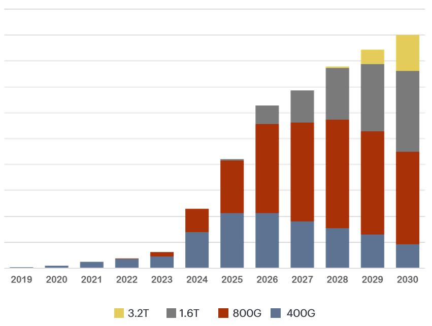
(source: Cignal AI, Fourth Quarter and Full Year 2025 – Optical Components Report)
Data center switching fabrics, which were previously centered on 100G/400G, have already rapidly transitioned globally to 800G (8x100G), and for next-generation large-scale AI clusters and 6G backbones 1.6T (8x200G) and 3.2T The introduction of high-speed modules is gaining momentum.
2. The Theory and Evolution of Signal Modulation: How to Carry Data on Light
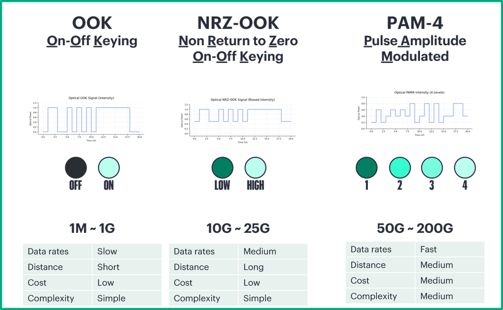
When switches or optical transceivers transmit data, the frequency bandwidth cannot be increased indefinitely, so the key technology becomes “how many bits to pack into a single wave (1 symbol).”.
[1] NRZ (Non-Return to Zero) - 1 bit per symbol
Voltage/Light Intensity Level: 2 Levels (High / Low) Level 1 ──────┐ ┌──────┐ │ │ │ Level 0 └──────┘ └────── Data : 1 0 1 0

[2] PAM4 (Pulse Amplitude Modulation 4-Level) - 2 bits per symbol
Voltage/Light Intensity Level: 4 steps (00, 01, 10, 11) Level 3 (11) ──┐ Level 2 (10) │ ┌── Level 1 (01) └──┐ │ Level 0 (00) └─┘ Data : 11 01 00 10

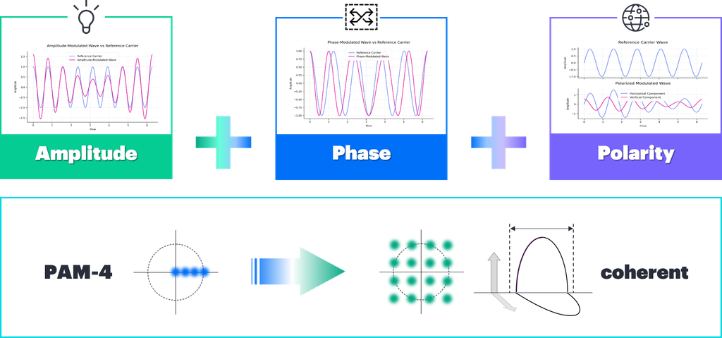
[3] Coherent - 4 to 6 bits or more per symbol (QPSK, 16-QAM)
Complex control of not only brightness (intensity) modulation but also the phase and polarization of light waves
Comparison of Principles and Applications by Modulation Technology
| Modulation technology | Principles and Transmission Characteristics | Advantages and Limitations | Major Application Areas |
| NRZ (OOK) | Signals distinguished by only two brightness levels, 0 and 1.. Simple ON/OFF method. | The circuit is simple and has a large noise margin, but high-frequency attenuation becomes severe as the speed increases.. | 1G ~ 100G (SFP+, SFP28, etc.) |
| PAM4 | Subdivide brightness into 4 levels and transmit 2 bits (00, 01, 10, 11) at a time.. | Double the transmission rate at the same clock frequency. However, since the signal level interval narrows, making it vulnerable to noise, signal recovery by the DSP is essential.. | 400G, 800G, 1.6T AIDC Internal Fabric |
| Coherent | Complex modulation utilizing phase and horizontal/vertical vibration directions (polarization) in addition to light intensity (amplitude). | Overcoming optical signal attenuation and chromatic dispersion enables ultra-long-distance transmission of thousands of km.. The optical element configuration is complex.. | 100G/400G/800G ZR/ZR+ (DCI, Metro, WAN) |
3. The Source of Transmission: Switch ASIC (SerDes) and 8-Lane (8-SerDes) Architecture
To understand optical transceivers, you must first know how signals originate from the switching silicon (ASIC) located in the center of the switch mainboard..
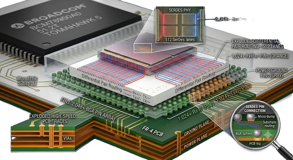
The internal core of an ASIC processes vast amounts of data in parallel. The core circuit that converts this into high-speed serial signals to output it to the port is the SerDes (Serializer/Deserializer).
[Switch ASIC Core (Parallel Data)]
             │ (512 High-Speed SerDes PHYs) ▼
[BGA Pin Array (Differential Pairs: Tx±, Rx±)]
             │ (Ultra-high-speed PCB Trace or Twinax Flyover) ▼
[Front-Panel Cage: OSFP / QSFP-DD]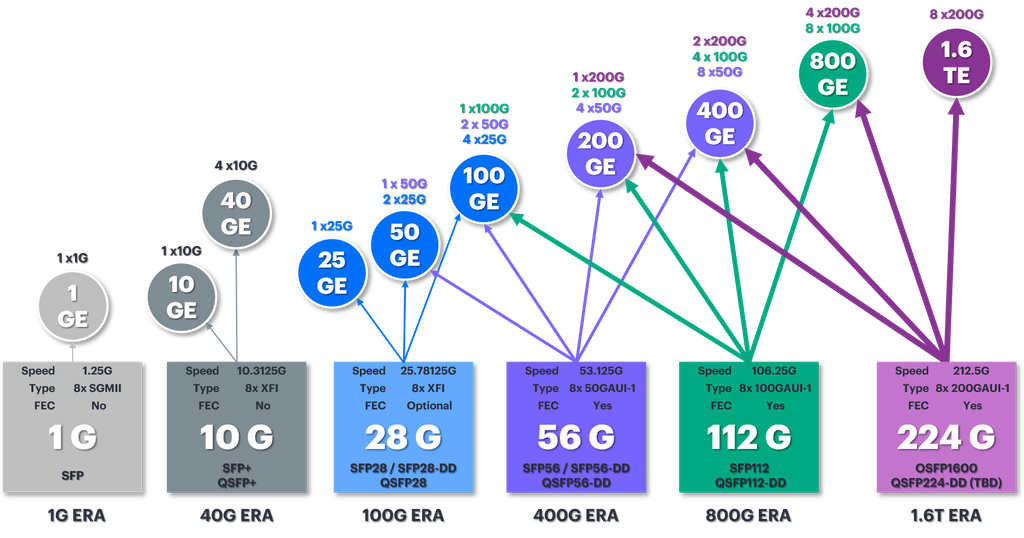
Tomahawk SerDes Evolution by Generation and Switch Capacity
| ASIC generation | Process Node | SerDes rate per lane | Total number of SerDes | switching bandwidth | Representative Port Configuration |
| Tomahawk 4 | 7nm | 50Gbps PAM4 | 512 | 25.6 Tbps | 64x 400G |
| Tomahawk 5 | 5nm | 100Gbps PAM4 | 512 | 51.2 Tbps | 64x 800G |
| Tomahawk 6 | 3nm | 200Gbps PAM4 | 512 | 102.4 Tbps | 64x 1.6T (128x 800G) |
In the case of the Broadcom Tomahawk 5, 512 SerDes lanes are integrated into a single chip, and signals are emitted through more than 2,048 BGA ball pins. One 800G port uses 8 SerDes lanes (8 x 100G = 800G).
- xR4 (DR4, FR4, etc.): The 8 lanes coming from the ASIC are combined 2:1 by the module's internal DSP/gearbox and compressed into 4 200G optical signals for transmission.
- xR8 (DR8, VR8, etc.): The 8 electrical signal lanes from the ASIC are directly connected and transmitted as 8 optical lanes inside the transceiver without a gearbox (conversion).
4. AIDC Internal Optical System: DR vs. FR Standards and MPO Connector Practical Applications
When connecting the AIDC internal fabric (Leaf-Spine), accurately matching the optical module and fiber specifications is fundamental to the design..
1) Comparison of DR vs FR vs LR Optical Characteristics
| standard | Maximum distance | fiber optics used | Optical transmission and reception method | Major Applications of AIDC |
| DR (Datacenter Reach) | 500m | Single Mode (SMF) | Parallel optical fiber (MPO-12/16) | Server ↔ Leaf, Leaf ↔ Spine internal standard |
| FR (Fiber Reach) | 2km | Single Mode (SMF) | Wavelength Division Multiplexing (CWDM4, LC) | Inter-Hall, large-scale campus fabric |
| LR (Long Reach) | 10km | Single Mode (SMF) | High-precision laser (LWDM4, LC) | Metro DCI and Core Routing |
2) MPO Connector Standard Classification and Connection Rules
AIDC actively utilizes Multi-Point Insertion (MPO) connectors to maximize single-port bandwidth..
MPO Classification by Deep
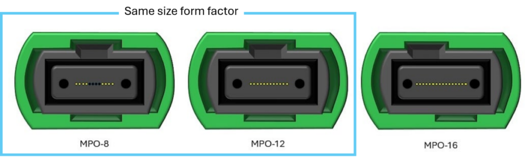
- MPO-8: It is a cost-effective connector with only 8 cores (4 Tx, 4 Rx) required for actual communication, optimized for 400G DR4 or 2x200G connections.
- MPO-12: It is an international standard 12-core ferrule specification, with 2 cores left empty at both ends and 8 cores in the center, or used in 4-SerDes dual links.
- MPO-16: 16 optical fibers are arranged in a single column 800G DR8 (8 Tx, 8 Rx) 및 1.6T DR8It accommodates it with a single cable.
- MPO-24 / MPO-32: This is a high-capacity trunk cable specification with increased core density using a dual-row structure.
- VSFF (SN-MT, MMC-16): It is a next-generation ultra-compact multi-core connector that can save more than three times the front panel area compared to MPO.
Guide Pin Fastening Rules (Male vs Female)
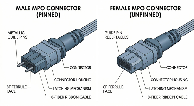
- The transceiver module port already has a guide pin built inside for precise alignment.
- Therefore, MPO patch cords that plug directly into switch/transceiver ports are Must be pinless UNPINNED (Female) typeYou must use [this]. If you force-plug a Pinned (Male) cable, the internal ferrule of the optical module will be damaged.
Side-face grinding: Full transition from UPC (Flat) to APC (8° bevel).
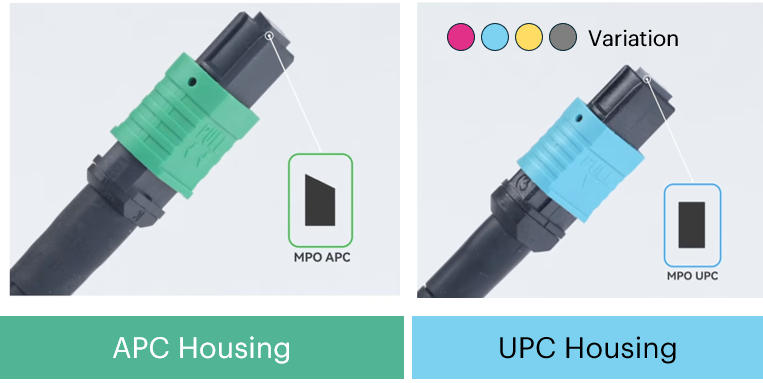
- In the 100G NRZ era, it was blue with a flat cross-section. UPC (Ultra Physical Contact) I mainly used connectors.
- However, high-speed PAM4 signals based on 100G/200G SerDes are very susceptible to optical return loss.
When faint reflected waves return, signal distortion (Reflection Noise) occurs, causing the link to break. - For this reason, single-mode MPO cables of 400G/800G or higher have their ends beveled at an 8-degree angle so that reflected waves refract out of the core. APC (Angled Physical Contact, Green Housing) The use of connectors has been standardized.
5. The Ideal and Reality of LPO: Why Did Switch Vendors Stop LPO?
Linear Pluggable Optics (LPO), which removes the DSP from inside the module to reduce power consumption and latency, garnered much anticipation at the time of its announcement..
[Standard Retimed Module]
Switch ASIC SerDes <───> [DSP (Signal Recovery/CDR)] <───> [Driver/Laser] (Power ~16W, Latency ~90ns)

[LPO (Linear Module)]
Switch ASIC SerDes <───────────────────────────> [Linear Driver/Laser] (Power ~8W, Latency ~4ns)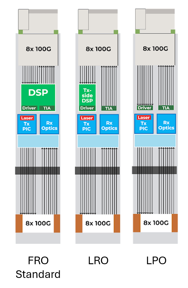
LPO had the advantage of saving 501 TP3T of power per module and lowering latency to the 4ns level by eliminating the DSP.
HPE also QFX5241-32OD We have pioneered the verification of LPO support on the same equipment.
Three technical limitations that put LPO implementation on hold in the field
- Multi-vendor Interoperability Failure: Since there is no DSP to correct the signal, the SerDes characteristics of the switch ASIC and the optical system of the optical module must be precisely matched on a 1:1 basis. If a Company B LPO module is plugged into a Company A switch, the link fails to connect, or an error (BER) occurs due to misalignment of host correction tuning via CMIS (Common Management Interface Specification).
- Physical Limitations in the 200G SerDes Generation: Signal correction was possible up to 100G SerDes (800G switches), but as it transitioned to 200G SerDes (1.6T switches), frequency noise and channel loss increased rapidly, making pure analog driving without a DSP impossible.
- Absence of telemetry: With the removal of the DSP, it becomes difficult to obtain precise optical reception quality monitoring (TDECQ, diagnostic data), leading to a decrease in the operational reliability of large-scale AIDCs.
6. Alternatives to Metro and DCI: Coherent and CORA Architectures
When connecting data centers (DCI) and regionally distributed clusters beyond the AIDC, it overcomes the limitations of simple optical intensity modulation (Direct Detection). Coherent Technology is being applied..
[Direct Detection (PAM4)]: Distinguishes between 0 and 1 by modulating only the brightness (intensity) of light (Transmission distance: hundreds of m to several km)

[Coherent Optics]: Controls light intensity (amplitude) + wave position (phase) + vibration direction (polarization) (Transmission distance: hundreds of km ~ 2,000 km+)
CORA (Converged Optical Routing Architecture)
In the past, to perform long-distance DWDM communication, it was necessary to set up a separate, expensive, dedicated transponder chassis outside the router..
HPE's CORA ArchitectureIt utilizes the JCO (Juniper Coherent Optics) series (400G/800G ZR/ZR+), which incorporates a coherent optical system into a small QSFP-DD form factor.
- Transponder Removal: Integrate the routing layer and DWDM transport layer by directly plugging a pluggable Coherent module into a router port (such as PTX10002).
- 0dBm High-Power ZR+: It minimizes the intervention of a separate external optical amplifier (EDFA) and transmits the laser directly into complex ROADM optical transmission networks.
- Operational Integration: Control optical wavelength, transmit power (Tx Power), and OSNR (Optical Signal-to-Noise Ratio) on a single screen on the router CLI/GUI through the router operating system (Junos OS) and AIOps tools (Routing Director, Apstra)[cite: 1].
3. The Dilemma of LPO (Linear Pluggable Optics) and Actual Alternative Technologies
Recently, the AIDC industry has been removing Digital Signal Processors (DSPs) from inside transceivers to reduce power consumption and latency. LPO (Linear Pluggable Optics) The technology has garnered attention. However, in actual enterprise and cloud infrastructure settings, a very cautious attitude is being taken regarding the adoption of LPO.
1) The Ideal and Realistic Limitations of LPO
more: By removing the DSP chipset, module power is reduced by 50% and latency is shortened to picoseconds (ps).
Realistic limitations:
- Lack of Interoperability: Since the DSP does not perform signal retiming, 1:1 analog tuning between the switch ASIC's SerDes and the transceiver optical system is essential. Ensuring compatibility in a multi-vendor environment is extremely difficult.
- Decreased Link Margin: Link stability drops significantly because signal error (BER) cannot be corrected due to optical connector contamination or increased distance.
- Limitations of remote monitoring: It is difficult to precisely collect diagnostic telemetry data due to the lack of a DSP.
2) A practical alternative chosen by the industry and HPE
[Short-term/Realistic Standard]  Ultra-low power DSP equipped Retimed Optics + Direct Liquid Cooling ↓
[Transitional Alternatives]    LRO (Linear Receive Optics: Maintain DSP only for Tx, linearize Rx) ↓
[Mid-to-long-term alternatives] CPO (Co-Packaged Optics: Direct integration of optical engine onto ASIC package)- Ultra-low Power Retimed Optics + Liquid Cooling: By maintaining the latest 3nm/5nm fine process DSP Signal integrity, interoperability, perfect telemetryThis is an approach that secures [performance/performance] and resolves generated heat using Direct-to-Chip Liquid Cooling (OSFP-RHS). (A key strategy for next-generation 1.6T switches such as the HPE QFX5250)
- LRO (Linear Receive Optics):This is a compromise that reduces power consumption by 25 to 301 TP3T while increasing signal stability compared to LPO by placing the DSP only in the transmitter (Tx) and removing the DSP only in the receiver (Rx).
- CPO (Co-Packaged Optics):This is a next-generation technology that moves away from the modular form factor and mounts the optical engine on the same package substrate as the switch main ASIC, suppressing electrical signal loss to the millimeter level.
4. The Evolution of Optical Modulation Technology: From Direct Detection to 'Coherent'
In optical communication, the method of carrying data in light (modulation) varies greatly depending on distance and speed. Direct Detection Method and Coherent Detection It is divided into different methods.
[Direct Detection (NRZ / PAM4)]
Distinguishes between 0 and 1 by simply turning light brightness (intensity) on and off ---> Due to its simple structure, it is mainly used for short distances/AIDC internal fabrics (up to ~10km).

[Coherent Optics (QPSK / 16-QAM, etc.)]
Controlling light amplitude, wave phase, and polarization—essential for long distances of thousands of km, DCI, metro, and ultra-high-capacity backbone networks.
Comparison of modulation methods
| Modulation technology | Principles and characteristics | Major Application Areas |
| NRZ (Non-Return to Zero) | 2-stage voltage/light intensity (0, 1) binary modulation. Simple but limited in speed scaling. | 1G ~ 100G Client Optics |
| PAM4 (Pulse Amplitude Modulation 4-Level) | Transmit 2 bits per clock with 4-stage light intensity levels (00, 01, 10, 11). | 400G/800G/1.6T AIDC Internal Fabric |
| Coherent | Combined control of light intensity + phase + polarization. Signal recovery by mixing with the receiver's local oscillator laser. | 100G/400G/800G ZR/ZR+ (DCI, WAN, Metro) |
5. Innovation in DCI and Metro Transmission: Coherent-based IPoDWDM and CORA
In the past, when connecting long-distance data center interconnects (DCI) and regionally distributed AI clusters, expensive external routers Dedicated chassis for DWDM transpondersWe had to set it up separately and wire the optical cables in a complex manner.
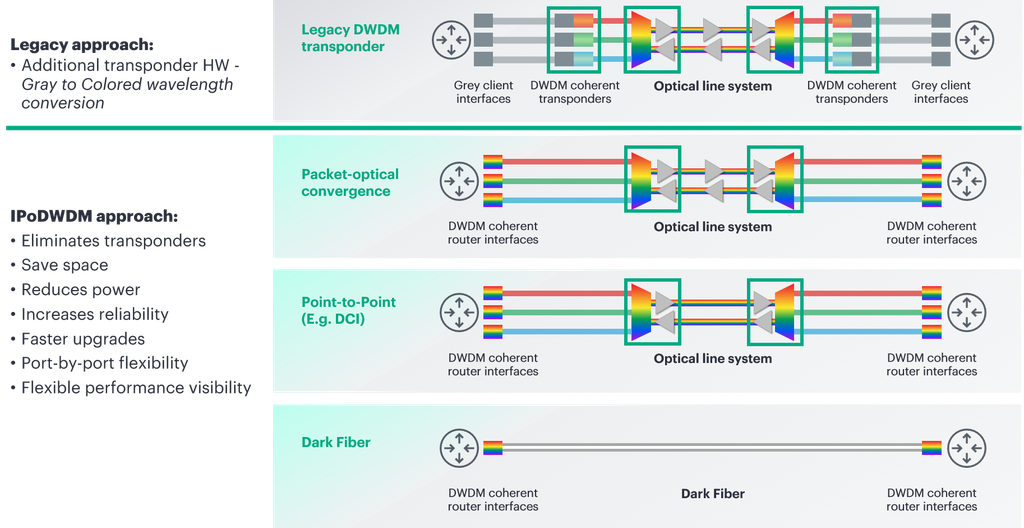
CORA (Converged Optical Routing Architecture)
HPE's CORA architecture directly mounts Coherent Pluggables (JCO400 / JCO800 ZR/ZR+), which miniaturize coherent optical technology, to router ports (PTX series, etc.). IPoDWDMIt realizes.
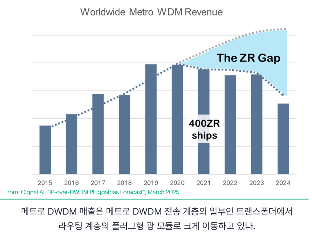
- 400ZR / 800ZR: Supports single-span (80–120 km) non-amplified DWDM transmission between DCI and campuses
- 400G/800G ZR+ (0dBm High Power): Power complex ROADM networks and ultra-long-distance backbone networks of thousands of km with direct router connection without external transponders through high-power coherent optical design
- CapEx/OpEx Reduction and Integrated Control: Saves power and space by removing the external chassis, and collectively controls Wavelength, Tx Power, and OSNR from the router console via software using Junos OS and Routing Director/Apstra.
6. Overcoming the Thermal Barrier: Heat Sink and Liquid Cooling Technology
The 800G and 1.6T optical modules are due to high-performance DSPs and laser drivers 20W to 40W or more per moduleIt consumes power. When dozens of modules are mounted on the front of a 1RU/2RU switch, heat of 1~2kW or more is generated from the optics alone, so air cooling (Fan Airflow) alone has reached its limit.
1) OSFP and Riding Heat Sink (RHS)
The next-generation 800G/1.6T form factor OSFPIt is designed to maximize airflow by mounting integrated heat dissipation fins (RHS) on the module surface or to make direct contact with the cooling block on the top of the switch chassis.
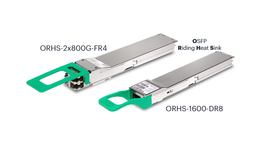
2) AIDC Liquid Cooling Architecture
- Direct-to-Chip (DLC) Cold Plate Linkage: The 100% immediately absorbs high heat by closely attaching a cold plate with circulating coolant to the top of the 64 OSFP-RHS transceiver cages as well as the switch ASIC chips. (e.g., HPE Juniper QFX5250-64OE-L with 102.4Tbps capacity)
- Immersion Cooling (Immersion Cooling): Sealed to prevent fluid penetration into the connector area for an environment where the entire equipment is immersed in insulating coolant Sealed Optical Interface Technology is applied.
💡 In conclusion... Vertically Integrated System Engineering
In the AIDC era, networks can no longer guarantee optimal performance and uninterrupted reliability using a mix-and-match approach for switch equipment, optical modules, and cables.
- high-speed serial signals Signal integrity (SI)
- Coherent DSP Tuning and Securing Link Margin
- Controlling high heat Liquid Cooling Thermal Management
- Routing Protocol (RPD) and AI-based integrated automation (AIOps)
All these elements must work together like a single organism.
Combining routing silicon, pluggable optics, and integrated light management software Vertically Integrated Systems Engineering The approach is the sure key to ensuring the scalability and resilience of mega-AI infrastructure.