When training AI models, networks are no longer mere pipes. In a collective communication environment where tens of thousands of GPUs exchange data, the loss of even a single packet becomes a critical bottleneck that delays the overall Joint Training Completion (JCT).
At last year's HPE Discover Barcelona, HPE and VIAVI Solutions presented a remarkable demonstration signaling a fundamental transformation of Ethernet.
Today, the one that has emerged as a rival to the InfiniBand UEC (Ultra Ethernet Consortium)From the background of its creation to perfectly overcoming the limitations of the existing RoCEv2 ‘Packet Trimming’ We will delve very deeply into the technology and the latest load balancing architecture.
Breaking the InfiniBand Monopoly: The Rise of UEC and the Mission
The massive AI data center network market, connecting tens of thousands of GPUs, has long been the exclusive domain of 'InfiniBand.' This was due to its powerful weapons of lossless and ultra-low latency. However, a closed vendor ecosystem, astronomical deployment costs, and scalability limitations that arise when the number of nodes exceeds 100,000 have begun to hold it back.
To counter this, in 2023, Global IT giants including HPE, Broadcom, Arista, Cisco, Intel, Meta, and Microsoft have come together under the Linux Foundation to form the Ultra Ethernet Consortium (UEC).I did.

Their goal is only one.
“Let’s create an AI-dedicated transmission technology that surpasses InfiniBand while maintaining Ethernet’s inherent openness and cost-effectiveness.”
And based on the recently announced UEC 1.0 specifications, Ultra Ethernet Transport (UTE), the core standard for next-generation AI fabrics, has finally been unveiled to the world.
The fatal Achilles' heel of existing Ethernet (RoCEv2)
RoCEv2, which currently underpins AI data center Ethernet, relies on Priority Flow Control (PFC) and DCQCN mechanisms to prevent packet loss.
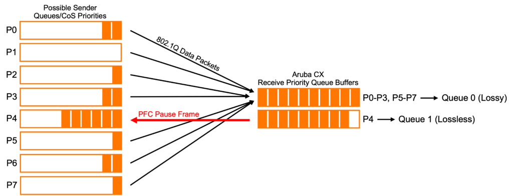
However, this passive congestion control method reveals clear limitations as the scale increases.
- Limitations of reaction speed (delay): The process of notifying the receiving side when the switch buffer fills up, and the receiving side then requesting the transmitting side to reduce the transmission speed, is itself too long.
- Blind packet drop: When traffic exceeds a threshold and the switch eventually has to drop packets, the conventional method literally 'evaporates' the packets without a trace.
- Timeout Penalty: The sending GPU has no way of knowing if the data it sent has been lost. Since it only starts retransmission after a timeout occurs much later, numerous GPUs remain idle during that time.
Technology Deep Dive: The Anatomy of UET Packet Trimming
To overcome these limitations, UET does not blindly discard packets.
‘It is a reverse approach of 'discarding data but preserving information' Packet trimmingWe introduced .
This technology operates within the network fabric with the following sophisticated mechanisms.
| step | Acting subject | Technical Mechanism (How it works) |
| 1. Congestion detection and trimming | UET switch | When the switch's Egress queue reaches saturation, the switch ASIC, instead of discarding the entire packet Cut out only the data payload The default header is preserved. |
| 2. Marking and Bypass (DSCP) | UET switch | In the truncated header packet Special DSCP (Priority Code) Marks the value. This packet moves immediately to the empty 'highest priority queue' instead of the blocked general data queue. |
| 3. Ultra-high-speed delivery | network fabric | The lightweight trimming packets pass through network bottlenecks like a high-speed toll pass and reach the destination GPU server (NIC) at the speed of light. |
| 4. Immediate Recognition and NACK | Receiver (Target NIC) | The receiving side analyzes the header of the incoming packet and “Exactly how many packets were lost” It immediately identifies the issue. It then sends a NACK (Negative Acknowledgment) to the sender to trigger the rapid retransmission of only that packet. |
💡 The core of this mechanism is ‘Telemetry of Congestion Signals’no see.
By detecting and recovering loss in sub-microseconds without the need to wait for timeouts, it prevents bandwidth waste due to packet retransmissions and guarantees extremely low and predictable latency.
Evolving Traffic Engineering: GLB, RALB, and Packet Spray
If packet trimming is responsible for 'post-recovery', intelligently distributing traffic to prevent the network from becoming blocked at all Traffic Engineering Technology is also evolving remarkably.
Going beyond the past dynamic load balancing (DLB) that simply monitored the status of switch ports, recent AI fabrics GLB와 RALBIt is equipped with a powerful weapon called.
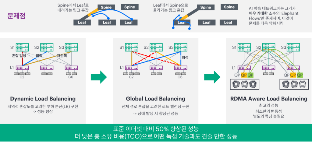
| Load balancing technology | aspect | Key to operation | Role in AI Networks |
| DLB (Dynamic) | Local (Switch perspective) | Monitor link usage within individual switches and distribute traffic to less congested ports. | Basic primary bottleneck avoidance |
| GLB (Global) | Fabric (Overall network perspective) | Collects telemetry from the entire fabric, calculates the end-to-end optimal path from the source to the destination, and distributes it. | Pre-emptive blocking of hidden congestion in core switches |
| RALB (RDMA-Aware) | Protocol (Application Perspective) | The switch directly understands the headers (QP, etc.) of RoCEv2/RDMA packets and safely distributes them in flow units to prevent them from being out of order. | Resolved persistent drop issues in legacy RoCEv2 environments |
These latest load balancing technologies combine with UET's transmission methods to form a perfect trinity.
- [Prior Coordination] Switch fabric is GLBDraw a map of the entire network through, RALBIt intelligently clears a path to prevent heterogeneous workload traffic from getting tangled.
- [Maximize Bandwidth] The UET transmitting side increases bandwidth efficiency to 100% by simultaneously scattering data like a watering can across multiple well-paved available paths through packet spraying.
- [Immediate Recovery] Nevertheless, the momentary collision that occurs is Packet trimmingThis activates to recover lost items without delay.
An architecture that combines the intelligent routing of switches with the innovative endpoint control of UETs is the foundation of next-generation AI data centers capable of scaling to 1 million nodes.
HPE Discover Barcelona: Proving Theory to Reality
These innovations of UET do not stop at simple specification documents.
HPE and VIAVI Solutions implemented this in actual hardware.
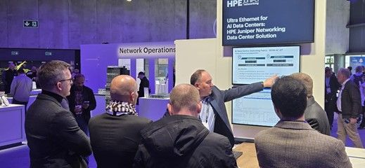
The demonstration is Broadcom's Tomahawk 5 ASICThis equipped Juniper QFX5240 Switch(800G 64-port) and VIAVI B3 800G ApplianceIt was conducted through.
- Real-time trimming verification: Even in extreme stress scenarios, the QFX5240 switch has been proven to perform packet trimming at the line-rate level and maintain stable traffic throughput.
- Coexistence of heterogeneous workloads: via the 800G port UET traffic and existing RoCEv2 traffic forwarded simultaneouslySurprisingly, the two protocols coexisted perfectly without packet drops or congestion propagation. This is strong evidence that gradual migration is possible while protecting legacy infrastructure.
- Job-ID based visibility: VIAVI's advanced instrumentation provides AI operators with powerful visibility by offering deep telemetry that can correlate latency and congestion causes at the individual job level.
Blueprint for Next-Generation AI Data Centers
AI infrastructure innovation has no end.
Subsequently, based on the Broadcom Tomahawk 6 supporting 1.6Tbps liquid-cooled Ethernet switching Juniper QFX5250 modelIt is also about to launch.
The collaboration between HPE and VIAVI sends a clear message to the industry.
The advantage is that you can gradually introduce UET, starting with the most congested AI cores, without the need for a complete Rip and Replace of the existing infrastructure.
Ultra Ethernet, which surpasses the performance of InfiniBand while providing the economics of an open ecosystem, has HPE and UEC's innovation at the center of its future.