

[ACP-DC Training #16] Ethernet VPN (EVPN) Add-ons
Previous postIf you have learned the basic concepts of EVPN fabric, let's now look at additional features to further optimize and enhance the EVPN environment.
Improves network performance by suppressing unnecessary broadcast/multicast frames occurring between leaf switches ARP and ND Suppression Let's look at how to configure the AOS-CX switch to efficiently handle multicast traffic over the VXLAN/EVPN fabric. We will also examine how to deploy IPv6 in a data center without changing the current IPv4 routing environment by using the existing IPv4 underlay network to transmit IPv6 traffic over the overlay.
ARP and ND suppression
EVPN ARP/ND Basic Operation
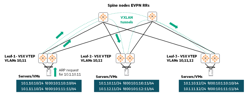
Basically, when a VTEP receives a BUM (Broadcast, Unknown Unicast, Multicast) frame containing ARP (IPv4 Address Resolution) and ND (IPv6 Neighbor Discovery) frames, it floods the frame to all local site-direction interfaces except the interface from which the packet entered. Additionally, the source VTEP duplicates this flooded frame and sends a copy to the destination IP address of each VXLAN tunnel belonging to that VXLAN. Upon receiving this, each destination VTEP floods the de-encapsulated internal Ethernet frame to all local site-direction interfaces of that VXLAN.
At this time, to prevent loops, destination VTEPs do not flood frames received in the tunnel to other VXLAN tunnels.
VXLAN ARP/ND suppression
Enabling ARP/ND suppression in a VXLAN EVPN distributed L3 gateway deployment environment makes the behavior much smarter.
When a host is discovered through a VTEP connected to the network, the host's MAC/IP binding information is shared with all other VTEPs in advance via MP-BGP (EVPN Route Type 2). Remote ARP entries shared via BGP in this way do not time out like a typical ARP cache and are removed from the network only when the corresponding MAC address is no longer visible at the source VTEP.
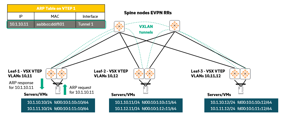
The figure above shows the VM connected to Leaf-1 (10.1.10.10The host connected to Leaf-2 (10.1.10.11This shows the sending of an ARP request (Broadcast) to find the MAC address of ).
Because Leaf-1 already has a mapping entry matching this request in its local cache, which was received via MP-BGP, After suppressing this ARP request without flooding it to other remote VTEPs, it then 10.1.10.11It immediately sends an ARP response (Proxy ARP Reply) to the local VM on its behalf. In this case, the response packet contains not VTEP's own MAC address, but Actual target host (10.1.10.11The MAC address of ) is contained as the source MAC. It will be delivered.
If the target address to be looked up does not exist in the local ARP/ND cache (e.g., a silent host that has never communicated), then the request packet is sent across the entire VXLAN fabric in the conventional manner to find the address. The same traffic suppression effect can be achieved for IPv6 ND requests (Neighbor Solicitation) for devices in the same VLAN and subnet.
VXLAN ARP/ND suppression configuration
ARP and ND suppression are disabled by default. To enable them config-evpn At the context level arp-suppression 및 nd-suppression Enter the command.
arp-suppression: Enables ARP suppression for EVPN-VXLAN globally across all Layer 2 VNIs configured in VTEP. If the destination address exists in the Neighbor cache, the switch responds directly to broadcast or unicast ARP requests. The default is disabled. If the destination IP/MAC is not in the cache, the switch forwards the ARP request through the VXLAN data plane for Neighbor resolution.nd-suppression: Enables ND suppression globally for EVPN-VXLAN. If the destination address exists in the cache, the switch directly responds to IPv6 multicast or unicast neighbor solicitation requests. The default is disabled.
As of the time of writing this document, the CX 8400 platform, based on an older architecture, does not support ARP and ND suppression due to hardware constraints.
Leaf EVPN Sample Configuration
switch(config)# evpn switch(config-evpn)# arp-suppression switch(config-evpn)# nd-suppression switch(config-evpn)# vlan 10 switch(config-evpn-vlan-10)# rd auto switch(config-evpn-vlan-10)# route-target import auto switch(config-evpn-vlan-10)# route-target export auto switch(config-evpn-vlan-10)# redistribute host-routeLLayer 2 Multicast Forwarding
Multicast with IGMP snooping
IGMP snooping is a multicast limiting (suppression) mechanism that operates on L2 devices to increase multicast forwarding efficiency.
It eavesdrops on and analyzes IGMP packets exchanged between hosts and routers to generate L2 multicast forwarding entries.
Enabling IGMP snooping completely changes the default behavior of multicast delivery in a VXLAN EVPN environment.
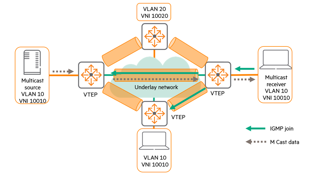
Basically, L2 multicast is treated as BUM traffic and is unconditionally flooded to all peer VTEPs in the same VNI. However, If IGMP snooping is enabled, the source VTEP close to the multicast source (sender) does not forward multicast traffic into the tunnel until it receives an IGMP Join (join request) packet from the remote.
Then, when it receives an IGMP Join from a specific remote VTEP, it only adds the corresponding VXLAN tunnel interface to the egress port list and starts sending multicast traffic only to that destination. In other words, In reality, only the VTEP to which the multicast receiver is connected receives the traffic.This prevents bandwidth waste.
Note that the IGMP Join packet sent by the receiver is flooded to all VTEPs in the same VNI because all switches need to know where the source and queryer are located.
IGMP snooping configuration
By default, IGMP snooping is disabled on AOS-CX switches.
To enable this, the VLAN configuration context (config-vlanEnter into ) ip igmp snooping enable You must enter a command. To disable ip igmp snooping disable Use options.
especially When using switches connected by a VSX pair as VTEP, redistribute local SVI information (redistribute local-sviMake sure to configure the switch to do so.Must do.
By doing this, EVPN Type-2 route advertising is enabled for the local IP and MAC addresses of the SVI interfaces corresponding to the EVPN-enabled VLAN, allowing remote hosts and switches to properly learn the MAC addresses of the IGMP queryers.
IGMP snooping activation
switch(config)# vlan switch(config-vlan)# ip igmp snooping enableEssential local SVI redistribution settings in a VSX pair environment
switch(config)# evpn switch(config-evpn)# redistribute local-sviIGMP Snooping Monitoring
To check IGMP snooping group details for a specific VLAN, including all IGMP snooping groups or source information show ip igmp snooping vlan group Use the command.
for example:
VTEP-1# show ip igmp snooping vlan 10 group 239.10.10.1 IGMP ports and group information for group 239.10.10.1 VLAN ID : 10 VLAN Name : VLAN10 Group Address : 239.10.10.1 Last Reporter : 100.3.3.109 Group Type : Filter V1 V2 Sources Sources Port Vers Mode Uptime Expires Timer Timer Forwarded Blocked --------- ---- ---- -------- ------- ----- ----- --------- ------- vxlan1(3.3.3.3) 2 EXC 5h 24m 3m 38s 3m 38s 0 0Multicast group through the output result above 239.10.10.1The output interface (Outgoing interface) for is peer 3.3.3.3VXLAN tunnel heading to (vxlan1(3.3.3.3)You can confirm that it is accurately mapped to ).
L3 Multicast Routing – PIM-SM
If the multicast routing protocol is not running, the network blocks IP multicast traffic transmitted by multimedia applications, etc., at the routing interface (L3 subnet) boundary.
PIM (Protocol Independent Multicast) is a family of multicast routing protocols that forms multicast distribution trees to deliver multicast source traffic to each subnet requesting traffic using protocols such as IGMP and MLD (for IPv6).
HPE recommends distributed L3 gateways (Symmetric IRBs) for data centers using EVPN, so PIM-Sparse Mode (PIM-SM) must be configured to route multicast between different subnets. This enables seamless communication between multicast sources and receivers even if they are scattered across different racks and subnets (VLANs).
PIM-SM can be configured on physical ports, VLAN interfaces (SVI), LAG interfaces, and loopback interfaces, and all settings operate within the context of the respective interface.
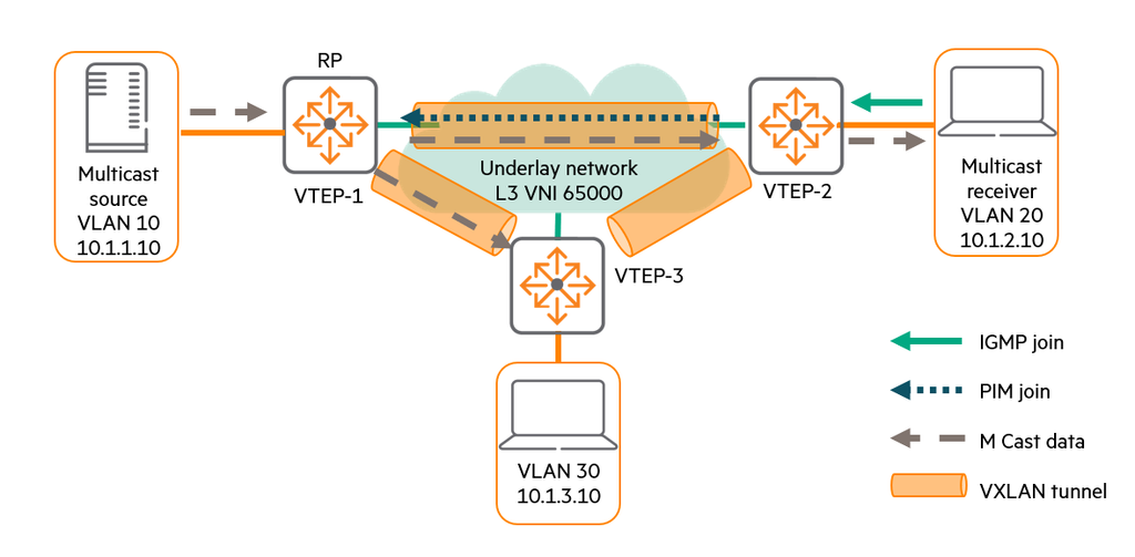
When PIM-SM is enabled, the VTEP closest to the multicast source transmits multicast packets only after receiving an explicit request (PIM Join) from the receiving side.
The example in the figure above shows that the source VTEP (VTEP-1) simultaneously for PIM-SM Rendezvous Point (RP – serves as a meeting plaza for multicast) Shows a topology that also serves a role:
- VTEP-2Receives an IGMP Join packet from one of the servers connected to it.
- VTEP-2is the RP and source through the tenant's public routing tunnel, L3 VNI (65000). VTEP-1to PIM Join Sends a packet.
- Received this VTEP-1is its own multicast routing table(
mrouteAdd Layer 3 VNI (65000) as an Outgoing interface to the table. - since VTEP-1It starts sending multicast traffic to peers belonging to this L3 VNI (65000), including VTEP-2 and VTEP-3.
- VTEP-2It routes the received multicast data to the VLAN (VLAN 20) where the server is located, and within it, IGMP and IGMP snooping handle the final Layer 2 multicast delivery. On the other hand, without a receiver VTEP-3It immediately drops the packet because there is no output interface to send the traffic.
Symmetric routing – RP away from the source
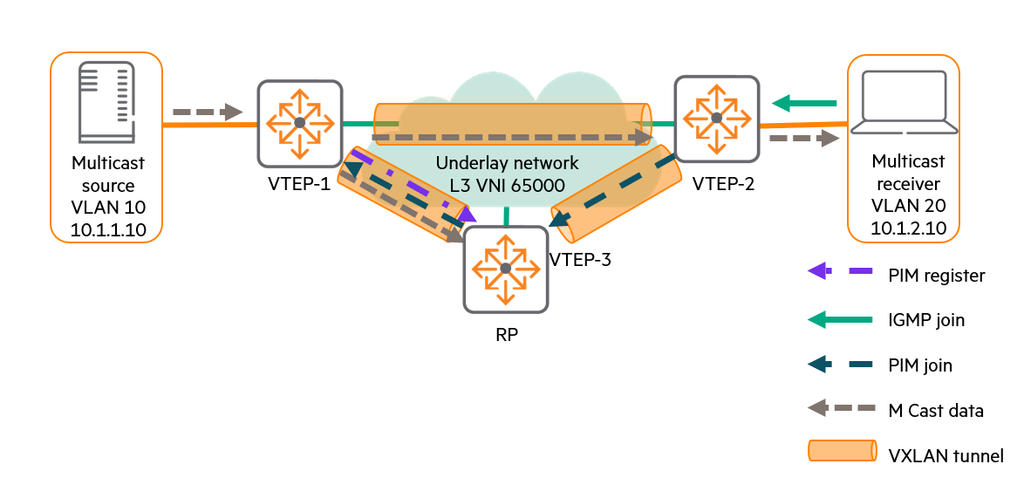
In the figure above, the rendezvous point (RP, VTEP-3) is physically separated from the multicast source (VTEP-1), and in this case, the processing procedure is slightly different:
- closest to the multicast source VTEP-1When this new multicast flow (stream) is received, first RP (VTEP-3Notifying ) that a new multicast flow has started PIM Register Sends the message via unicast.
- After that, the new multicast receiver (server) its switch (VTEP-2If you send an IGMP Join to ), VTEP-2is RP(VTEP-3Toward ) PIM Join Creates and sends a message.
- playing the RP role VTEP-3Receives this PIM Join message and has the actual source VTEP-1It delivers (Proxy) to instead.
- VTEP-1His
mrouteAdd L3 VNI (65000) to the table as an output interface and start forwarding multicast streams to all VTEPs belonging to that L3 VNI (switch to the optimal path, SPT).
Multicast Design Considerations in VSX Environments (VSX – Design considerations)
In environments requiring multicast routing, it is best practice to use a distributed gateway (symmetric routing) when configuring switches paired with VSX as leaf nodes. In this case, the VSX switches ip pim vsx-virtual-neighbor You must configure the command to enable both switches (Primary and Secondary) to operate as Designated Routers (DRs) simultaneously.
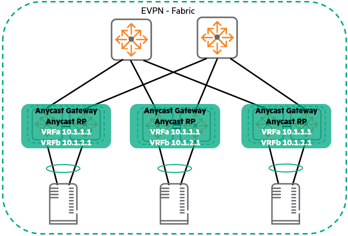
In addition, to eliminate single point of failure (SPOF) and distribute the load, it is best practice to configure two or more switches as a rendezvous point (RP) using anycast IP (Anycast RP).
VSX Border VTEP with L2 extension – Multicast Source Side Scenario (VSX Border VTEP with L2 extension – source case)
Now, let's look at a scenario where the VSX pair switch operates as a VTEP (VTEP-1) close to the multicast source.
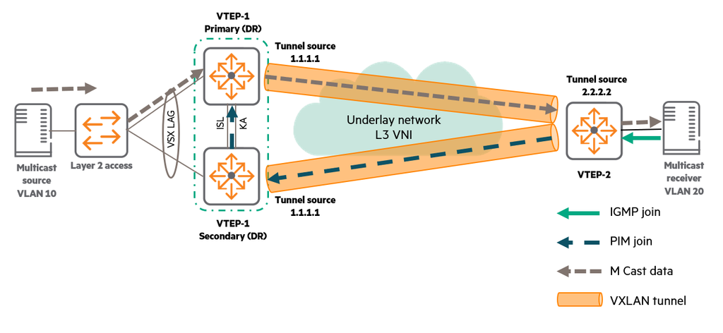
Please remember that both switches in the VSX pair operate as DR as previously configured.
- remote VTEP-2It receives an IGMP Join packet from the server and learns that a new multicast receiver has been created.
- VTEP-2It sends a PIM Join message to the source side, VTEP-1 (VSX pair).
- Due to the underlay's ECMP (Equal Cost Multipath) routing, either the Primary or Secondary switch of the VSX receives this PIM Join packet.
- After whichever switch receives this Join message processes the message, Send a copy to your VSX peer via the ISL (Inter-Switch Link)....through this, both switches have their own.
mrouteSynchronize to include the L3 VNI identically in the table output interface list.
Subsequently, when VTEP-1 (VSX pair) receives the actual multicast traffic and forwards it to the remote VTEP-2, in order to prevent duplicate packet transmission Different operation methods depending on the switch hardware model series...shows:
- HPE Aruba Networking CX 6300 Series, CX 6400 Series, CX 8360 Series Switches: The very switch that actually receives the multicast traffic from the server (via LAG hashing, etc.) forwards it directly to the VXLAN tunnel.
- HPE Aruba Networking CX 8320 Series, CX 8325 Series, CX 8400 Series Switches: If the VSX pair is properly activated and in sync, Only the Primary switch It forwards multicast traffic to VTEP-2. The secondary switch forwards multicast traffic only in failure situations where the ISL link is broken and even Keep-Alive fails.
VSX Border VTEP with L2 Extension – Multicast Receiver Scenario
This time, let's look at the receiver-side behavior when a multicast receiver sends an IGMP Join message to its gateway (VSX pair):
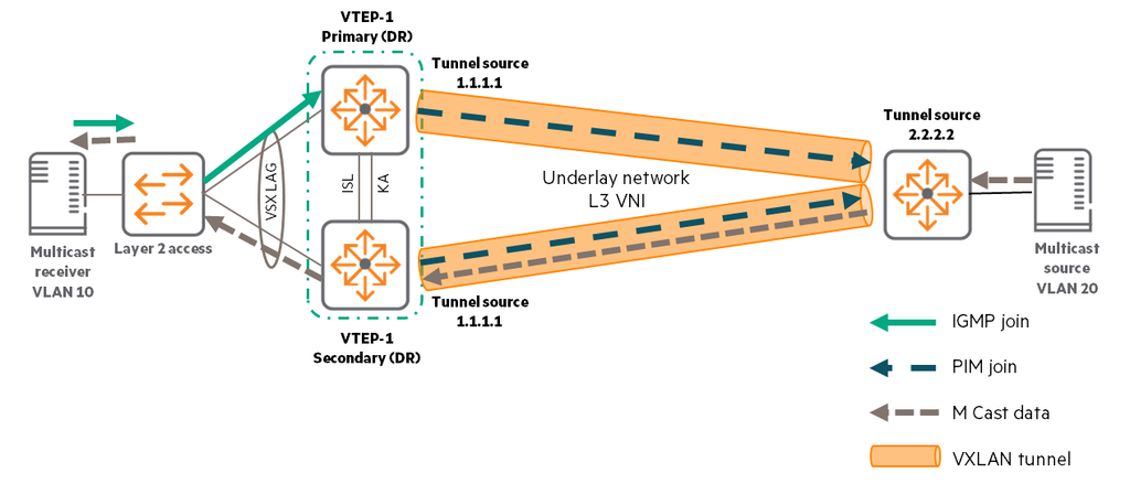
- Due to Link Aggregation (MC-LAG) load balancing, one of the VSX switches receives IGMP Join traffic.
- The switch that receives the traffic processes it and notifies the VSX peer. Then Both the Primary and Secondary switches generate PIM Join packets and send them to the remote peer's VTEP.do.
- The source-side peer VTEP is
mrouteAdd the L3 VNI to the output interface list of the table and start routing and sending multicast traffic. - Due to the ECMP underlay, one of the receiving VSX switches receives the encapsulated multicast traffic, and the very switch that receives the packet deencapsulates it and routes the multicast to the server VLAN.
PIM-SM – Leaf Switch Configuration
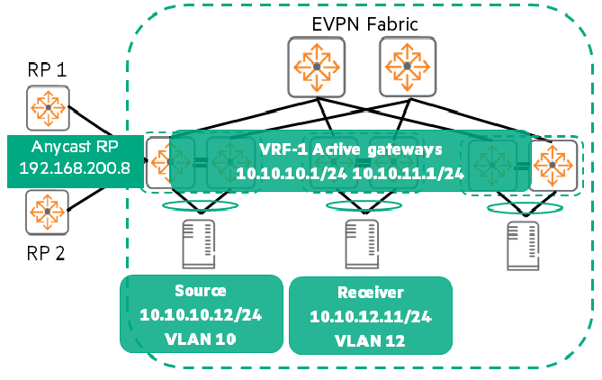
There is no difference in commands between configuring PIM-SM in a traditional data center network and configuring it in a VXLAN/EVPN environment.
By default, PIM is disabled at the global level.
To enable this in the configuration context, first for the tenant VRF router pim [vrf ] After entering the command, enable commands and rp-addressYou must enter the (Rendezvous Point Address).
After enabling at the global level, enable PIM on all VLAN interfaces (SVI) where multicast sources and receivers are expected to exist (ip pim-sparse enable) must be done.
At this time, to manage multicast delivery within the VLAN, the SVI IGMP(ip igmp enableAlso composedYou must not forget that you have to do it.
Leaf1a# router pim vrf VRF1 enable rp-address 192.168.200.8 ! interface vlan10 vrf attach VRF1 ip address 10.10.10.2/24 active-gateway ip mac 12:00:00:00:01:00 active-gateway ip 10.10.10.1 ip pim-sparse enable ip igmp enableMulticast Verification
- PIM Neighbor Check: The first step in monitoring a multicast routing environment is
show ip pim neighbor [ ] [all-vrfs | vrf ] [vsx-peer]It involves using a command to check PIM neighbors. As shown in the example below, all PIM neighbors are displayed, and in particular, remote neighbors192.168.11.5is not a physical port VXLAN tunnel (L3 VNI)vni100001Reachable via )Please note the point that...
Leaf1a# show ip pim neighbor vrf VRF1 PIM Neighbor VRF : VRF1 Total number of neighbors : 2 IP Address : 10.10.10.3 Interface : vlan10 Up Time (HH:MM:SS) : 3 days 02:49:07 Expire Time (HH:MM:SS) : 00:01:44 DR Priority : 1 Hold Time (HH:MM:SS): 00:01:45 IP Address : 192.168.11.5 Interface : vni100001 Up Time (HH:MM:SS) : 3 days 02:49:43 Expire Time (HH:MM:SS) : 00:01:45 DR Priority : 1 Hold Time (HH:MM:SS): 00:01:45- Check Multicast Routing Table (mroute): The second verification step is
show ip mroute [all-vrfs | vrf ] [vsx-peer]This involves checking the multicast routing table using a command. In the example below, the incoming interface (Incoming interface)govlan10However, this means that the multicast source is directly connected to VLAN 10 of this VTEP. Next, the outgoing interface (Outgoing Interface List)govni100001It is indicated as such, which means a multicast receiver connected to another remote VTEP requests this multicast flow and forwards it to the L3 VNI tunnel (forwardingIt means a heavy responsibility. - Check RP settings: Another useful command for monitoring multicast routing environments is
show ip pim rp-set [all-vrfs | vrf ] [vsx-peer]You can verify the currently applied RP address.
Leaf1a# show ip mroute vrf VRF1 IP Multicast Route Entries VRF : VRF1 Total number of entries : 1 Group Address : 239.10.10.10 Source Address : 10.10.10.12 Neighbor : Incoming interface : vlan10 Outgoing Interface List : Interface State ----------- ---------- vni100001 forwardingLeaf1a# show ip pim rp-set vrf VRF1 VRF: VRF1 Status and Counters - PIM-SM Static RP-Set Information Group Address Group Mask RP Address Override --------------- --------------- --------------- -------- 224.0.0.0 240.0.0.0 192.168.200.8 NoIPv6 routing at the overlay network
IPv6 support in VXLAN EVPN
Switches running AOS-CX software version 10.6 or higher support IPv6 routing in overlay networks of VXLAN EVPN fabrics.
At this time The underlay network operates as standard IPv4, and internal IPv6 packets are encapsulated in an outer IPv4 header for transmission.Therefore, there is absolutely no need to deploy IPv6 anew on the underlay infrastructure. VTEPs, which act as gateways for servers, can operate as pure IPv6-only or IPv4/IPv6 dual-stack.
Current software uses a server address allocation method SLAAC (Stateless Address Autoconfiguration) and supports static address allocation, but, IPv6 DHCP relay (DHCPv6 relay) is not supported. In addition, the AOS-CX switch enables communication by exchanging IPv6 paths between different VRFs. IVRL (Inter-VRF Route Leaking) It also supports the feature.
Additionally, hardware models that support IPv6 routing in the overlay CX 6300, CX 6400, CX 8325, CX 8360, and CX 8400 series It is a switch.
Data center distributed L3 gateway use case
The most representative example of using IPv6 routing in an overlay is In the case of introducing IPv6 to the server side without modifying the current IPv4 routing environment at all in a data center that already has a stable underlay network using IPv4This method allows you to easily deploy pure IPv6 overlays or dual-stack overlays while maintaining existing underlay routing (OSPF, BGP, loopback IPv4 address schemes, etc.). The software supports both distributed and centralized routing, and HPE recommends distributed routing (Symmetric IRB) as a best practice.
Figure 12-10: Distributed L3 Gateway
Dual-stack configuration
When configuring IPv6 on switches bundled as a VSX pair, use a Global Unicast Address for each switch's own SVI address, and must use a Link Local IP for the Active Gateway address shared by the two switches.fe80:: You must use the band.
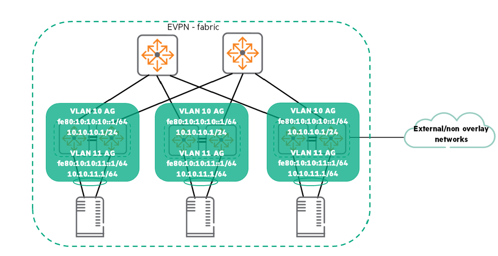
interface vlan10 vrf attach VRF1 ip address 10.1.10.2/24 active-gateway ip mac 12:00:00:00:01:00 active-gateway ip 10.1.10.1 ipv6 address 2001:db8:1:10::2/64 active-gateway ipv6 mac 12:00:00:00:01:00 active-gateway ipv6 fe80:10:1:10::1At this time, the IPv4 active gateway and the IPv6 active gateway Must have the same virtual MAC address (
12:00:00:00:01:00Use )Must do.
Enabling SLAAC
As mentioned earlier, current software does not support DHCPv6 relay.
Therefore, to automatically assign an IPv6 address to the server SLAACYou can use. The switch transmits Router Advertisement (RA) You must use messages to inform the servers of network prefixes, RDNSS (recursive DNS server addresses), etc.
ipv6 nd prefix 2001:db8:1:10::/64 ipv6 nd ra dns server 2001:db8:1::2 ipv6 nd ra dns search-list arubanetworks.com no ipv6 nd suppress-ra no ipv6 nd suppress-ra dnssl no ipv6 nd suppress-ra rdnssThe example above is a sample configuration that allows the switch to provide information including the prefix, DNS search list, and RDNSS to servers via RA messages. The detailed roles of each command are as follows:
IPv6 and prefix: The routing switch specifies the IPv6 network prefix to include in the RA message transmitted from the corresponding interface. IPv6 hosts use this prefix contained in the RA to auto-configure their global unicast addresses. The auto-configured host address is created by combining the advertised 64-bit prefix with the interface identifier (such as 64-bit EUI-64) found in the host's current link-local address.IPv6 nd ra dns server: Configure the IPv6 address of the default recursive DNS server (RDNSS) to be included in the RA message transmitted from the interface.ipv6 nd ra dns search-list: Configure the DNS search list (DNSSL) to be included in the RA transmitted from the interface.- DNSSL includes DNS suffix domain names that are automatically appended when querying short, unqualified domain names.
- You can add multiple DNS domain names to DNSSL by entering this command repeatedly.
- Up to 8 server addresses are allowed.
ipv6 nd suppress-ra: Configure the interface to suppress (block) IPv6 router advertisement (RA) transmission (since this is often suppressed by default in SVI, to send RA, as in the example above)noform(no ipv6 nd suppress-raYou must restore (enable) IPv6 router advertisement and option delivery by entering ).nd suppress-raDetailed options of:DNSSL: Suppresses the transmission of DNSSL options in RA messages.MTU: Suppresses the transmission of MTU options in RA messages.RDNSS: Suppresses the transmission of RDNSS options in RA messages.
MP-BGP Configuration (MP-BGP)
Because the IPv4 underlay carries IPv6 packets from the overlay network, the default MP-BGP EVPN session configuration between the spine and leaf is exactly the same as the IPv4 configuration of the preceding Ethernet VPN module.
However, to allow BGP to advertise the tenant's IPv6 address and prefix as an EVPN, the IPv6 address family under the corresponding VRF (address-family ipv6 unicastActivate ) and redistribute directly connected networks (redistribute connectedYou must do this.
router bgp 65001 # (Basic EVPN BGP configuration omitted - no difference from MP-BGP EVPN configuration for IPv4) # vrf VRF1 address-family ipv6 unicast redistribute connectedIPv6 Overlay Validation
After activating the IPv6 address family show ipv6 neighbors {all-vrfs | vrf } [vsx-peer] Enter a command to monitor whether the IPv6 neighbor list (ND table) is being properly populated with IPv6 neighbors learned from other remote VTEPs.
When new neighbors and prefixes are advertised by MP-BGP, the corresponding entries can be found in the IPv6 routing table.
In the IPv6 routing table example below, the VXLAN peer 192.168.11.5L3 VNI of (IPv4 underlay address) 100001remote server through 2001:db8:1:12:80a0:5d8b:f992:cb1d/128Please note that you can reach.
Check IPv6 Neighbors
Leaf1# show ipv6 neighbors vrf VRF1 IPv6 Address MAC Port Physical Port State VRF -------------------------------- ----------------- ------ ------------- --------- ---- fd00:10:1:10:404b:2df2:1c01:c8b1 00:50:56:8e:cf:69 vlan10 lag2 reachable VRF1 fe80::f4af:f785:51cb:403c 00:50:56:8e:cf:69 vlan10 lag2 reachable VRF1 fd00:10:1:10:50e6:7e3c:6b9d:5f36 00:50:56:8e:cf:69 vlan10 lag2 reachable VRF1 fd00:10:1:10:98ff:91d8:a9a8:f80 00:50:56:8e:cf:69 vlan10 lag2 reachable VRF1 fd00:10:1:10:74aa:c745:850c:a2ed 00:50:56:8e:cf:69 vlan10 lag2 reachable VRF1 fd00:10:1:10:4cad:545c:70e4:e6de 00:50:56:8e:cf:69 vlan10 lag2 reachable VRF1 Total Number Of IPv6 Neighbors Entries Listed- 6.Check IPv6 Routing Tables (Routes)
Leaf1# show ipv6 route vrf VRF1 Displaying ipv6 routes selected for forwarding '[x/y]' denotes [distance/metric] fd00:10:1:10::/64, vrf VRF1 via vlan10, [0/0], connected 2001:db8:1:12::/64, vrf VRF1 via 192.168.11.5[vrf default], [200/0], bgp, encap vxlan, l3vni 100001 2001:db8:1:12:80a0:5d8b:f992:cb1d/128, vrf VRF1 via 192.168.11.5[vrf default], [200/0], bgp, encap vxlan, l3vni 100001IVRL (Inter-VRF Route Leaking) Configuration and Verification
IVRL – Configuration
To allow an IPv6 overlay environment to communicate with an external network or a public service VRF, you must use IVRL (Inter-VRF Route Leaking) to mutually leak (exchange) routes between the IPv6 overlay VRF and the external VRF. The example below shows the configuration of a Border VTEP (Leaf-1) connected to the outside and a Compute VTEP (Leaf-2) connected to an internal server.
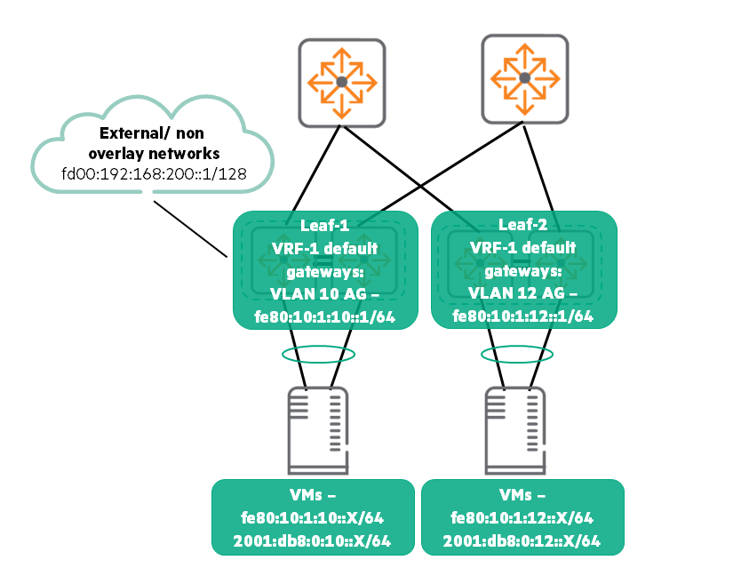
Border switch-in Leaf-1In this case, a unique RD is configured for each VRF, and then the EVPN environment and internal VRF(VRF1Route targets for EVPN to allow importing and exporting routes between )route-target ... evpnCreates ). Then, two VRF(VRF1과 SERVICESTo control local route leaks between ) address-family ipv6 unicastConfigures.
The key point here is Two VRFsVRF1과 SERVICES) between route-target import와 export The point is that by setting the values to intersect (invert) each other, it allows paths to leak between the two VRFs.no see(65001:601과 65001:605(cross-matching with each other).
For other standard leaf switches, only slight modifications are required. For example, the internal switch Leaf-2는 SERVICES Without needing to know VRF directly, IPv6 VRF(VRF1Basic between ) and EVPN environment route-target import/export evpn(65001:1If you have only ), you can use the external path that Leaf-1 advertises via EVPN as is.
Border VTEP / Leaf 1 Settings:
vrf VRF1 rd 192.168.1.3:1 route-target export 65001:1 evpn route-target import 65001:1 evpn address-family ipv6 unicast route-target export 65001:601 route-target import 65001:605 vrf SERVICES rd 192.168.1.3:5 address-family ipv6 unicast route-target export 65001:605 route-target import 65001:601Compute VTEP / Leaf 2 Setup:
vrf VRF1 rd 192.168.1.5:1 route-target export 65001:1 evpn route-target import 65001:1 evpnIVRL – Validating
One way to verify IVRL operation is to check the IPv6 routing table.
The example below shows the output results for the previous settings.
Border Leaf (Leaf 1) is locally leaked SERVICES VRF(via 2001:192:168:4::[vrf SERVICES]External host via ) 2001:192:168:200::1/128While it has a path to, the remote switch Leaf 2is a border reef Leaf 1(192.168.11.3)'s VXLAN tunnel(l3vni 100001through ) Please verify that the path to the external host has been successfully learned.
Border VTEP Leaf 1 Routing Table:
Leaf1# show ipv6 route vrf VRF1 '[x/y]' denotes [distance/metric] 2001:db8:1:10::/64, vrf VRF1 via vlan10, [0/0], connected 2001:db8:1:12::/64, vrf VRF1 via 192.168.11.5[vrf default], [200/0], bgp, encap vxlan, l3vni 100001 2001:db8:1:12:80a0:5d8b:f992:cb1d/128, vrf VRF1 via 192.168.11.5[vrf default], [200/0], bgp, encap vxlan, l3vni 100001 2001:192:168:200::1/128, vrf VRF1 via 2001:192:168:4::[vrf SERVICES], [200/0], bgpCompute VTEP Leaf 2 Routing Table:
Leaf2# show ipv6 route vrf VRF1 '[x/y]' denotes [distance/metric] 2001:db8:1:10::/64, vrf VRF1 via 192.168.11.3[vrf default], [200/0], bgp, encap vxlan, l3vni 100001 2001:db8:1:10:b1fa:b585:979f:ac99/128, vrf VRF1 via 192.168.11.3[vrf default], [200/0], bgp, encap vxlan, l3vni 100001 2001:db8:1:12::/64, vrf VRF1 via vlan12, [0/0], connected 2001:192:168:200::1/128, vrf VRF1 via 192.168.11.3[vrf default], [200/0], bgp, encap vxlan, l3vni 100001In this module, starting with minimizing broadcast traffic through ARP/ND suppression IGMP Snooping and PIM-SM-based Multicast Control, and utilizing the existing IPv4 underlay as is IPv6 Overlay and IVRL (Route Leaking between VRFs) We have now examined the configuration as well. Moving beyond securing basic connectivity, it is now possible to operate an advanced EVPN data center fabric that reduces bandwidth waste and reliably accommodates multimedia traffic and next-generation IPv6 environments.
In the next session, as the next step in the journey of the data center network built in this way, we will explore Fabric Composer software for fabric operations and automation.